Isuzu D-Max / Isuzu Rodeo (TFR/TFS). Manual — part 1664
1-42 HEATING AND AIR CONDITIONING
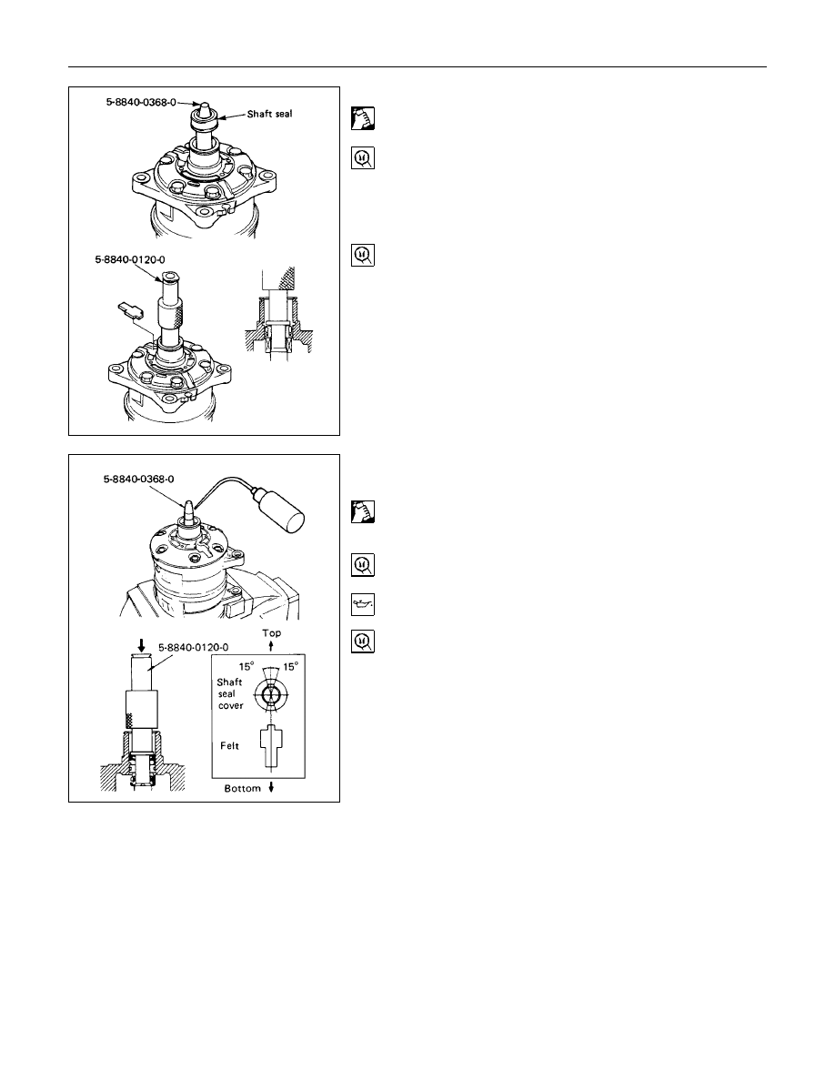
13.Shaft Seal Assembly
1) Clean the sealing portion of the compressor and shaft
seal.
2) Install the shaft seal guide onto the end of the drive
shaft.
3) Shaft Seal Guide: 5-8840-0368-0 (J-34614)
4) Apply new compressor oil to the shaft seal guide.
5) Install the shaft seal onto the compressor drive shaft
head by using shaft seal installer.
Shaft Seal Installer: 5-8840-0120-0 (J-33942)
15.Shaft Seal Cover (If so equipped)
16.Felt (If so equipped)
Clean the sealing portion of the compressor and shaft seal
cover.
Install the shaft seal guide onto the end of the drive shaft.
Shaft Seal Guide: 5-8840-0368-0 (J-34614)
Apply new compressor oil to the shaft seal guide.
Install the shaft seal cover onto the drive shaft by using
shaft seal installer.
The installation position of the shaft seal cover is shown in
the illustration.
Shaft Seal Installer: 5-8840-0120-0 (J-33942)
HEATING AND AIR CONDITIONING 1-43
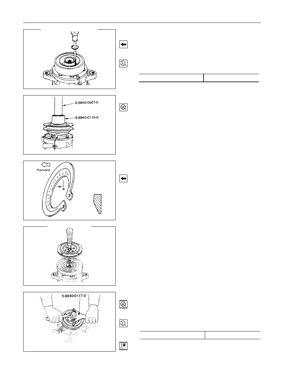
17.Field Coil
18.Lead Wire Connector
Install the field coil to the compressor.
Lead wire must be facing up.
Tighten the field coil fixing screws to the specified torque.
N
⋅
m (kgf
⋅
m/Ib
⋅
ft)
Torque
5.0 (0.5/3.6)
19.Pulley Asssembly
Using pulley installer and drive handle to install the pulley
assembly.
Pulley Installer: 5-8840-0118-0 (J-33940)
Drive Handle: 5-8840-0007-0 (J-8092)
20.Cover (If so equipped)
21.Snap Ring
Install the snap ring with the inside indented portion facing
out.
22.Shim(s)
23.Drive Plate
Install the drive plate to the compressor drive shaft together
with the original shim(s).
Press the drive plate by hand.
24.Drive Plate Bolt
Using drive plate holder to prevent the drive plate from
rotating.
Drive Plate Holder: 5-8840-0117-0 (J-33939)
Tighten the bolt to the specified torque.
N
⋅
m (kgf
⋅
m/Ib
⋅
ft)
Torque
15 (1.5/11)
After tightening the bolt, check to be sure the pulley rotates
smoothly.
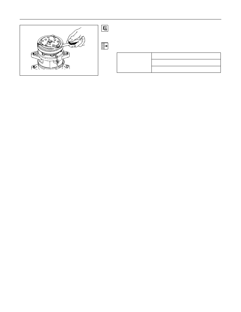
1-44 HEATING AND AIR CONDITIONING
Check to be sure that the clutch clearance is between 0.3 -
0.6 mm (0.01 - 0.02 in).
If necessary, install adjusting shim(s).
Adjusting shims are available in the following thickness.
0.1 mm (0.0039 in)
Thickness
0.3 mm (0.0118 in)
0.5 mm (0.0197 in)
HEATING AND AIR CONDITIONING 1-45
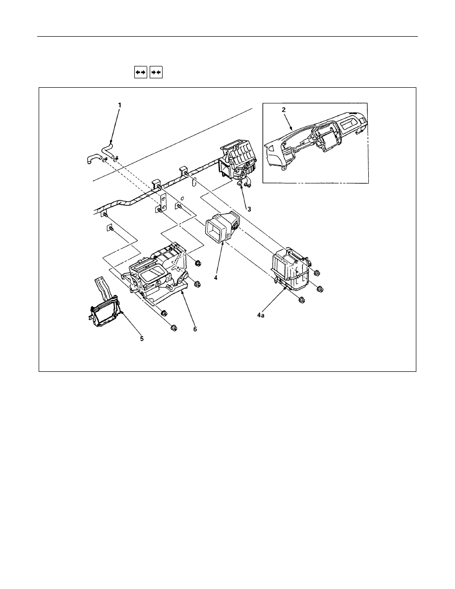
HEATER UNIT
REMOVAL AND INSTALLATION
This illustration is based on LHD model
Removal Steps
▲
1. Heater hose
▲
2. Instrument panel assembly
3. Resistor connector
4. Duct
4a. Evaporator (A/C only)
5. Instrument panel stay
6. Heater unit
Installation steps
6. Heater unit
5. Instrument panel stay
4a. Evaporator (A/C only)
4. Duct
3. Resistor connector
▲
2. Instrument panel assembly
1. Heater hose
Нет комментариевНе стесняйтесь поделиться с нами вашим ценным мнением.
Текст