Isuzu D-Max / Isuzu Rodeo (TFR/TFS). Manual — part 316

AUTOMATIC TRANSMISSION (AW30-40LE) 7A-113
TCM VOLTAGE CHECK
TCM voltage check is done to check for transmission and
transmission control module (TCM) problems which cannot
be detected by self-diagnosis.
Additionally, it serves as a back-up check for self-
diagnosis.
Measure the voltage drop and make a continuity test for
each of the sensors, solenoids, and switches.
If the voltage is within the specified range and continuity
exists, that particular area of the TCM and automatic
transmission assembly is normal.
If voltage deviation or lack of continuity is discovered,
disconnect the applicable parts and check each of them
individually.
This will allow you to determine the trouble location (TCM,
automatic transmission unit, or another area of the
vehicle).
826RY00017
Inspection Tool
Use a circuit tester to measure voltage and circuit
continuity.
Insert the test probes from the connector wiring side. TCM
terminals are extremely small.
Wrap a piece of thin wire around the probe of tester.
This will make measurement easier.
NOTE:
TCM is located in the behind instrument panel of the
driver’s compartment.
TCM Voltage Check Procedure
1. Remove the TCM.
2. Turn the ignition switch on. Do not start the engine.
3. Measure the voltage at the terminal.
Refer the following table for the specified voltage
ranges.

7A-114 AUTOMATIC TRANSMISSION (AW30-40LE)
TCM STANDARD VOLTAGE
Terminal
Check circuit
+ –
Measuring condition
Voltage (V)
Throttle fully closed (Idling)
0.25
∼ 0.45
C79-6 C79-28
Throttle fully opened (WOT)
3.47
∼ 4.56
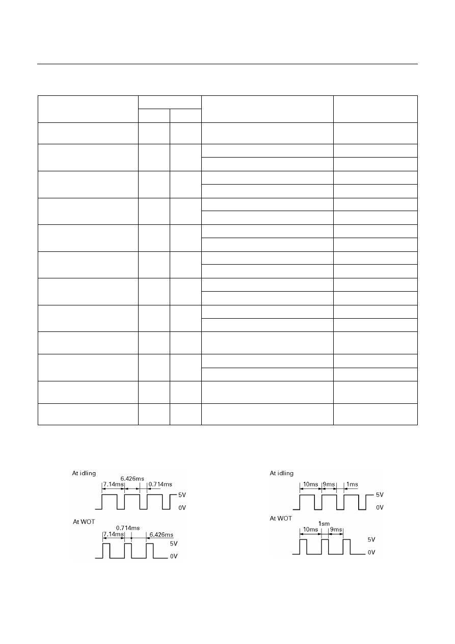
Throttle position sensor
(UBS)
C79-19 C79-28 Key switch ON
4.75
∼ 5.25
Throttle fully closed (Idling) (*1)
4.4
∼ 4.6
Throttle position sensor
(TFR/S)
C79-6
C78-15
or –19
Throttle fully opened (WOT) (*1)
0.4
∼ 0.6
Output revolution sensor
C79-4 C79-16 Engine idling in gear
0
∼ 3
Input revolution sensor
C79-5 C79-17 Engine idling
0
∼ 3
Speed meter sensor
C79-7
C78-15
or –19
Vehicle speed 1
∼ 2 km/h (Pulse
check)
Less than 1.4
⇔ Greater than 9
Depress brake
7
∼ 16
Brake switch
C78-18
C78-15
or –19
Release brake
Less than 1
O/D switch position ON
(O/D OFF lamp OFF)
Less than 1
O/D switch
C79-3 C78-15
or –19
O/D switch position OFF
(O/D OFF lamp ON)
7
∼ 16
Selector “P” range
7
∼ 16
Neutral start switch
(P)
C79-2
C78-15
or –19
Selector all ranges except “P”
Less than 1
Selector “R” range
7
∼ 16
Neutral start switch
®
C79-1
C78-15
or –19
Selector all ranges except “R”
Less than 1
Selector “N” range
7
∼ 16
Neutral start switch
(N)
C79-9
C78-15
or –19
Selector all ranges except “N”
Less than 1
Selector “D” range
7
∼ 16
Neutral start switch
(D)
C79-8
C78-15
or –19
Selector all ranges except “D”
Less than 1
Selector “2” range
7
∼ 16
Neutral start switch
(2)
C79-21
C78-15
or –19
Selector all ranges except “2”
Less than 1
Selector “L” range
7
∼ 16
Neutral start switch
(L)
C79-20
C78-15
or -19
Selector all ranges except “L”
Less than 1
Engine revolution signal
C79-15
C78-15
or -19
Engine idling
Less than 1.4
⇔ 9 ∼ 16
Diagnosis terminal
C79-24 C78-15
or -19
Self-diagnosis ON
0
∼ 1.5
Power pattern switch OFF (NORMAL)
8
∼ 16
Power pattern switch
C79-23
C78-15
or -19
Power pattern switch ON (POWER)
Less than 1.4
Switch OFF
8
∼ 16
Winter select switch
C79-13
C78-15
or -19
Switch ON
Less than 1.4
Electrical source (Battery)
C78-13
C78-15
or -19
―
9
∼ 16
AUTOMATIC TRANSMISSION (AW30-40LE) 7A-115
TCM STANDARD VOLTAGE (Cont’d)
Terminal
Check circuit
+ –
Measuring condition
Voltage (V)
Electrical source (Ignition)
C78-20
C78-15
or -19
Key switch ON
9
∼ 16
Oil temperature warning lamp ON
Less than 1
Oil temperature warning
lamp
C79-11
C78-15
or -19
Oil temperature warning lamp OFF
8
∼ 16
“CHECK TRANS” lamp ON
Less than 1
“CHECK TRANS lamp”
C79-10
C78-15
or -19
“CHECK TRANS” lamp OFF
8
∼ 16
Power lamp ON
Less than 1
Power lamp (UBS)
C79-22
C78-15
or -19
Power lamp OFF
8
∼ 16
Winter lamp ON
Less than 1
Winter lamp (UBS)
C79-12
C78-15
or -19
Winter lamp OFF
8
∼ 16
OFF (3rd or O/D)
Less than 1
Solenoid S1
C78-4
C78-15
or -19
ON (1st or 2nd)
8
∼ 16
OFF (1st or O/D)
Less than 1
Solenoid S2
C78-3
C78-15
or -19
ON (2nd or 3rd)
8
∼ 16
OFF (Lock up OFF)
Less than 1
Lock up solenoid SL
C78-12
C78-15
or -19
ON (Lock up ON)
8
∼ 16
Pressure control solenoid
C78-11 C78-8
At throttle pressure changing
Less than
1
⇔ 8-16
ATF temperature 20
°
4.70
Oil temperature sensor
C79-18 C79-27
ATF temperature 80
°C
3.65
Tech 2 diagnosis terminal
(J1850)
C78-6 C78-15
or -19
On diagnosis communication
0-1.5
⇔
6.25-8.0
Throttle position sensor
(ground) (UBS)
C79-19
C78-15
or -19
Key switch ON
-0.1
∼ 0.1
*1: Reference (Oscilloscope waveform)
(TFR/S)
(’01 TFR for Thailand)
7A-116 AUTOMATIC TRANSMISSION (AW30-40LE)
ON-VEHICLE SERVICE
UBS
242R200004
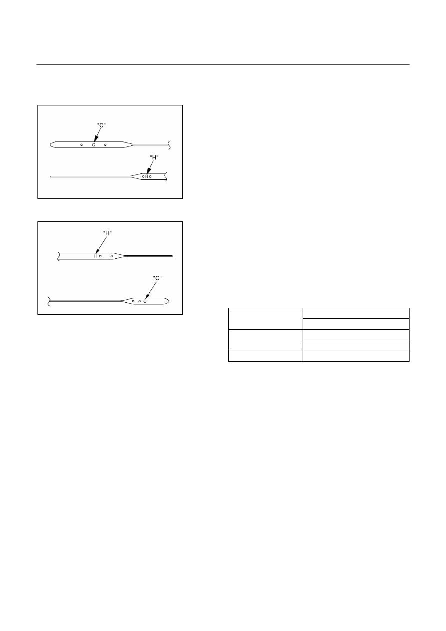
TRANSIMISSION FLUID LEVEL AND
CONDITION
Park vehicle on level ground and set parking brake.
With the engine idling, move the shift lever through all
positions from "P" to "L", then return to position "P".
Check to see If the level of fluid comes to "HOT" range of
about 80
°C (176°F) on the dipstick gauge.
If the level of fluid is too low, replenish to bring it to
maximum level in "HOT" range.
Inspection of fluid condition
If the ATF is black or smells burnt, replace it.
ATF REPLACEMENT
NOTE:
Do not overfill.
1. Remove the drain plug from oil pan and drain the fluid.
2. Reinstall the drain plug securely.
Torque: 19 N・・・・m (1.9 kg・・・・m/14 Ib・・・・ft)
3. With the engine OFF, add new fluid through the filler
tube.
5.2 liter (UBS and TFR/S)
Drain and refill
4.5 liter (’01 TFR)
8.7 liter (UBS and TFR/S)
Dry fill
8 liter (’01 TFR)
Fluid
BESCO ATF Ⅲ
TF
242R200005
4. Start the engine and shift the selector into all position
from "P" through "L", and then shift into "P".
5. With the engine idling, check the fluid level. Add fluid
up to the "COLD" level on the dipstick.
6. The ATF level must be checked again for correct level
with the "HOT" level.
NOTE:
To prevent fluid leaks, the drain plug gasket must be
replaced each time this plug is removed.
Нет комментариевНе стесняйтесь поделиться с нами вашим ценным мнением.
Текст