Isuzu D-Max / Isuzu Rodeo (TFR/TFS). Manual — part 317

AUTOMATIC TRANSMISSION (AW30-40LE) 7A-117
NEUTRAL START SWITCH INSPECTION
Inspection
With a circuit tester, make a continuity test on the neutral
start switch with the moving piece set in each position.
Terminal
Position
1
4
3
5 2 6 8 7
9
P
○
○
○
○
R
○
○
N
○
○
○
○
D
○
○
2
○
○
L
○
○
249RY00010
○ ○ Continuity
Removal
Preparation:
Disconnect negative (-) battery cable.
1. Remove rear sound cover (UBS).
2. Remove the rear side ATF cooler pipe from the
transmission elbow.
3. Disconnect neutral start switch connector.
4. Unstake the lock washer, and then remove the shaft
nut.
5. Remove the neutral start switch.
Installation
To install, follow the removal steps in the reverse order,
noting the following points;
Torque:
Nut – 7 N・・・・m (0.7 kg・・・・m/61 Ib・・・・in)
Bolt – 13 N・・・・m (1.3 kg・・・・m/113 Ib・・・・in)
249RY00008
Adjustment
1. Loosen the neutral start switch bolt and set the shift
selector to the “N” range.
2. Align the groove and neutral basic line.
3. Hold in position and tighten the bolt.
Torque: 13 N・・・・m (1.3 kg・・・・m/113 Ib・・・・in)
7A-118 AUTOMATIC TRANSMISSION (AW30-40LE)
310RW020
BRAKE SIGNAL INSPECTION
Check that the brake light comes on when the brake pedal
is depressed.
F07RY00017
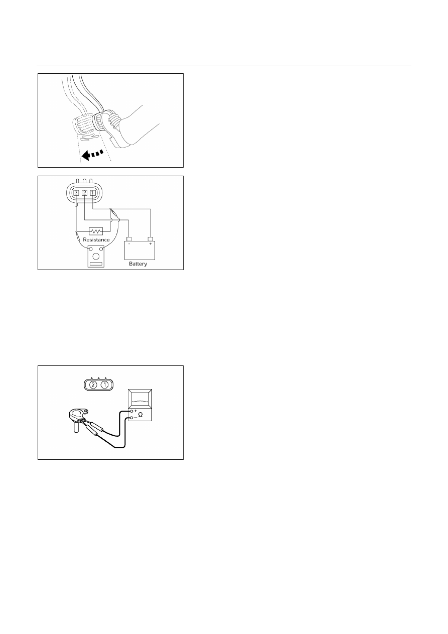
VEHICLE SPEED SENSOR INSPECTION
1. Connect the vehicle speed sensor connector terminal
(1) to the battery ( +) terminal and terminal (2) to the
battery (-) terminal.
2. Connect a resistance of 1.3k ohm to 5k ohm (1.4W or
more) between terminals (1) and (3).
NOTE:
Be extremely careful not to connect the battery (+)
terminal to the terminal (3).
This may damage the vehicle speed sensor.
3. Rotate the shaft of the vehicle speed sensor slowly and
measure the voltage at both ends with a digital tester.
The voltage, with one rotation of shaft, fluctuates four
times in the following range: 10 to 14V ⇔ 2V or less.
Replace the sensor when the result of inspection is
found abnormal.
F07RY00018
INPUT AND OUTPUT REVOLUTION
SENSOR INSPECTION
1. Disconnect the input and output revolution sensor
connector.
2. Use an ohmmeter to measure the resistance between
terminals 1 and 2.
Standard resistance
Input revolution sensor: 387 – 473 Ω
Ω
Ω
Ω (at 20℃
℃
℃
℃, 4×
×
×
×2)
560 – 680 Ω
Ω
Ω
Ω (at 20℃
℃
℃
℃, 4×
×
×
×4)
Output revolution sensor: 560 – 680 Ω
Ω
Ω
Ω (at 20℃
℃
℃
℃)

AUTOMATIC TRANSMISSION (AW30-40LE) 7A-119
UBS
F07RY00019
TF
F07L100005
PATTERN SELECT SWITCH INSPECTION
Inspect that there is continuity between each terminals.
UBS
225R200003
TF
225L200001
OVERDRIVE SWITCH INSPECTION
Inspect that there is continuity between each terminals.
7A-120 AUTOMATIC TRANSMISSION (AW30-40LE)
220L100001
SOLENOID INSPECTION
1. Resistance
check
・ Using an ohmmeter, check the resistance between
each terminals (S1/S2/SL) and body.
Solenoid S1, S2 and lock-up solenoid resistance:
11 – 15 Ω
Ω
Ω
Ω (at 20℃
℃
℃
℃)
(Reference) 12 – 16 Ω
Ω
Ω
Ω (at 40℃
℃
℃
℃)
・ Using an ohmmeter, check the resistance between
each terminals (STH) and (STHG).
Pressure control solenoid resistance:
5 – 5.6 Ω
Ω
Ω
Ω (at 20℃
℃
℃
℃)
(Reference) 5.4 – 6.1 Ω
Ω
Ω
Ω (at 40℃
℃
℃
℃)
NOTE:
If the pressure control solenoid resistance is not
within specification, replace the valve body
assembly.
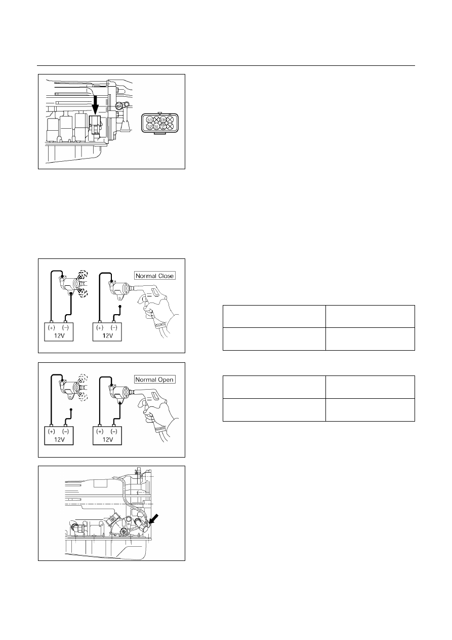
2. Operation
check
Check the solenoid operation by blowing into an oil
hole as shown in the figure.
Solenoid S1 and S2 (Normal close type)
When battery terminal is
disconnected
No air leaks
When battery terminal is
connected
Air passes through
244RX00001
Lock-up solenoid S3 (Normal open type)
When battery terminal is
disconnected
Air passes through
When battery terminal is
connected
No air leaks
244RY00005
249L100001
ATF TEMPERATURE SENSOR
INSPECTION
1. Disconnect the front side ATF cooler pipe from the
elbow and remove the elbow.
2. Remove the ATF temperature sensor from the
transmission case.
3. Place the ATF temperature sensor in a container of
ATF.
Нет комментариевНе стесняйтесь поделиться с нами вашим ценным мнением.
Текст