Isuzu D-Max / Isuzu Rodeo (TFR/TFS). Manual — part 225

ENGINE DRIVEABILITY AND EMISSIONS
6E–141
7
Using the DVM and check the TPS power supply
circuit.
1. Ignition “On”, engine “Off”.
2. Disconnect the TPS connector.
3. Check the circuit for short to voltage circuit.
Was the DVM indicated specified value?
Approximately
5.0V
Go to Step 9
Go to Step 8
8
Repair the short to voltage circuit between the ECM
and TPS.
Was the problem solved?
—
Verify repair
Go to Step 14
9
Using the DVM and check the TPS signal circuit.
1. Ignition “On”, engine “Off”.
2. Disconnect the TPS connector.
3. Check the circuit for short to power supply circuit.
Was the DVM indicated specified value?
Less than 1V
Go to Step 10
Repair faulty
harness and
verify repair
10
Using the DVM and check the TPS ground circuit.
1. Ignition “On”, engine “Off”.
2. Disconnect the TPS connector .
3. Check the circuit for short to power supply circuit.
Was the DVM indicated specified value?
Less than 1V
Go to Step 11
Repair faulty
harness and
verify repair
Step
Action
Value(s)
Yes
No
V
E68
2
2
E60(J1)
E68
15
3
V
E68
1
V
E68

6E–142
ENGINE DRIVEABILITY AND EMISSIONS
11
Using the DVM and check the TPS ground circuit.
Breaker box is available:
1. Ignition “Off”, engine “Off”.
2. Install the breaker box as type A. (ECM
disconnected) Ref. 6E-80.
3. Disconnect the TPS connector.
4. Check the circuit for open circuit.
Was the problem found?
Breaker box is not available:
1. Ignition “Off”, engine “Off”.
2. Disconnect the TPS connector and ECM
connector.
3. Check the circuit for open circuit.
Was the problem found?
—
Repair faulty
harness and
verify repair
Go to Step 14
12
Substitute a known good TPS and recheck.
Was the problem solved?
—
Go to Step 13
Go to Step 14
13
Replace the TPS.
Is the action complete?
—
Verify repair
—
14
Is the ECM programmed with the latest software
release?
If not, download the latest software to the ECM using
the “SPS (Service Programming System)”.
Was the problem solved?
—
Verify repair
Go to Step 14
15
Replace the ECM.
Is the action complete?
IMPORTANT: The replacement ECM must be
programmed. Refer to section of the Service
Programming System (SPS) in this manual.
Following ECM programming, the immobiliser system
(if equipped) must be linked to the ECM. Refer to
section 11 “Immobiliser System-ECM replacement” for
the ECM/Immobiliser linking procedure.
—
Verify repair
—
Step
Action
Value(s)
Yes
No
32
1
E68
32
1
E60(J1)
E68
ENGINE DRIVEABILITY AND EMISSIONS
6E–143
DIAGNOSTIC TROUBLE CODE (DTC) P0131 O
2
SENSOR CIRCUIT LOW
VOLTAGE (BANK 1 SENSOR 1)
Condition for setting the DTC and action taken when the DTC sets
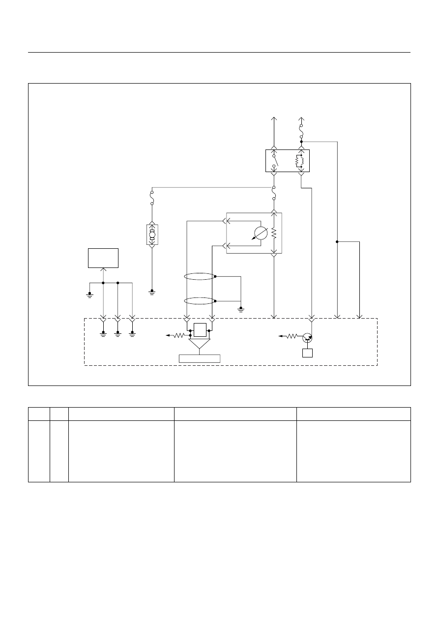
Circuit Description
The engine control module (ECM) supplies a bias
voltage of about 450 mV between the heated oxygen
sensor (HO2S) signal and low circuits. The oxygen
sensor varies the voltage within a range of about 1000
mV when the exhaust is rich, down through about 10
mV when exhaust is lean. The ECM constantly monitors
the HO2S signal during “Closed Loop” operation and
compensates for a rich or lean condition by decreasing
or increasing injector pulse width as necessary. If the
Bank 1 HO2S 1 voltage remains excessively low for an
extended period of time, Diagnostic Trouble Code
P0131 will be set.
Diagnostic Aids
Check for the following conditions:
• Heated oxygen sensor wiring - The sensor pigtail
may be routed incorrectly and/or contacting the
exhaust system. Also, check for shorts to ground,
shorts to battery positive and open circuits.
Code
Type
DTC Name
DTC Setting Condition
Fail-Safe (Back Up)
P0131
A
O
2
SensorCircuit Low Voltage (Bank 1
Sensor 1)
1. No DTC relating to MAP sensor, TPS,
EVAP purge, ECT sensor, CKP sensor,
VSS, injector control circuit and ignition
control circuit.
2. Engine coolant temperature is more than
60°C.
3. O
2
sensor bank 1 output voltage is below
50mV in “Closed Loop” condition.
“Open Loop” fuel control.
µP
V
Ign
-
+
Crankshaft
Position
Sensor
J1-1 J1-2 J1-17
Battery
Voltage
Battery
Voltage
2.0
WHT
ECM
10A
450
mV
A/D Converter
Vcc
+5V
-
+
TIMING
COVER
J2-6
J2-21
Fuel
Pump
FUEL
PUMP
20A
2.0
BLK
2.0
BLK/
BLU
Fuel
Pump
Relay
O
2
SENSOR
10A
Heated
O
2
Sensor
0.85
RED/
WHT
0.5
GRN/
WHT
0.5
RED/
WHT
0.5
BLU/
WHT
0.5
BLU
0.5 PNK
J2-31
J2-11
J2-2
J2-18
M
Engine
Control
Module
(ECM)

6E–144
ENGINE DRIVEABILITY AND EMISSIONS
• Poor ECM to engine block grounds.
• Fuel pressure - The system will go lean if pressure is
too low. The ECM can compensate for some
decrease. However, if fuel pressure is too low, a
Diagnostic Trouble Code P0131 may be set. Refer to
Fuel System Diagnosis.
• Lean injector(s) - Perform “Injector Balance Test.”
• Vacuum leaks - Check for disconnected or damaged
vacuum hoses and for vacuum leaks at the intake
manifold, throttle body, EGR system, and PCV
system.
• Exhaust leaks - An exhaust leak may cause outside
air to be pulled into the exhaust gas stream past the
HO2S, causing the system to appear lean. Check for
exhaust leaks that may cause a false lean condition
to be indicated.
• Fuel contamination - Water, even in small amounts,
can be delivered to the fuel injectors. The water can
cause a lean exhaust to be indicated. Excessive
alcohol in the fuel can also cause this condition. For
the procedure to check for fuel contamination, Refer
to Fuel System Diagnosis.
Diagnostic Trouble Code (DTC) P0131
O
2
Sensor Circuit Low Voltage (Bank 1 Sensor 1)
Step
Action
Value(s)
Yes
No
1
Was the “On-Board Diagnostic (OBD) System Check”
performed?
—
Go to Step 2
Go to On Board
Diagnostic
(OBD) System
Check
2
1. Connect the Tech 2.
2. Review and record the failure information.
3. Select “F0: Read DTC Infor By Priority” in “F0:
Diagnostic Trouble Code”.
Is the DTC P0131 stored as “Present Failure”?
—
Go to Step 3
Refer to
Diagnostic Aids
and Go to Step
3
3
1. Using the Tech2, ignition “On” and engine “Off”.
2. Select “Clear DTC Information” with the Tech2 and
clear the DTC information.
3. Operate the vehicle and monitor the “F5: Failed
This Ignition” in “F2: DTC Information”.
Was the DTC P0131 stored in this ignition cycle?
—
Go to Step 4
Refer to
Diagnostic Aids
and Go to Step
4
4
Check for poor/faulty connection at the O
2
sensor or
ECM connector. If a poor/faulty connection is found,
repair as necessary.
Was the problem found?
—
Verify repair
Go to Step 5
5
Using the DVM and check the O
2
sensor circuit.
1. Ignition “On”, engine “Off”.
2. Disconnect the O
2
sensor connector.
3. Check the circuit for short to heater ground or
ground circuit.
Was the DVM indicated specified value?
Approximatly
450mV
Go to Step 7
Go to Step 6
C56(J2)
E77
31
21
6
V
2
1
E77
Нет комментариевНе стесняйтесь поделиться с нами вашим ценным мнением.
Текст