Isuzu D-Max / Isuzu Rodeo (TFR/TFS). Manual — part 950
REAR AXLE 4B-37
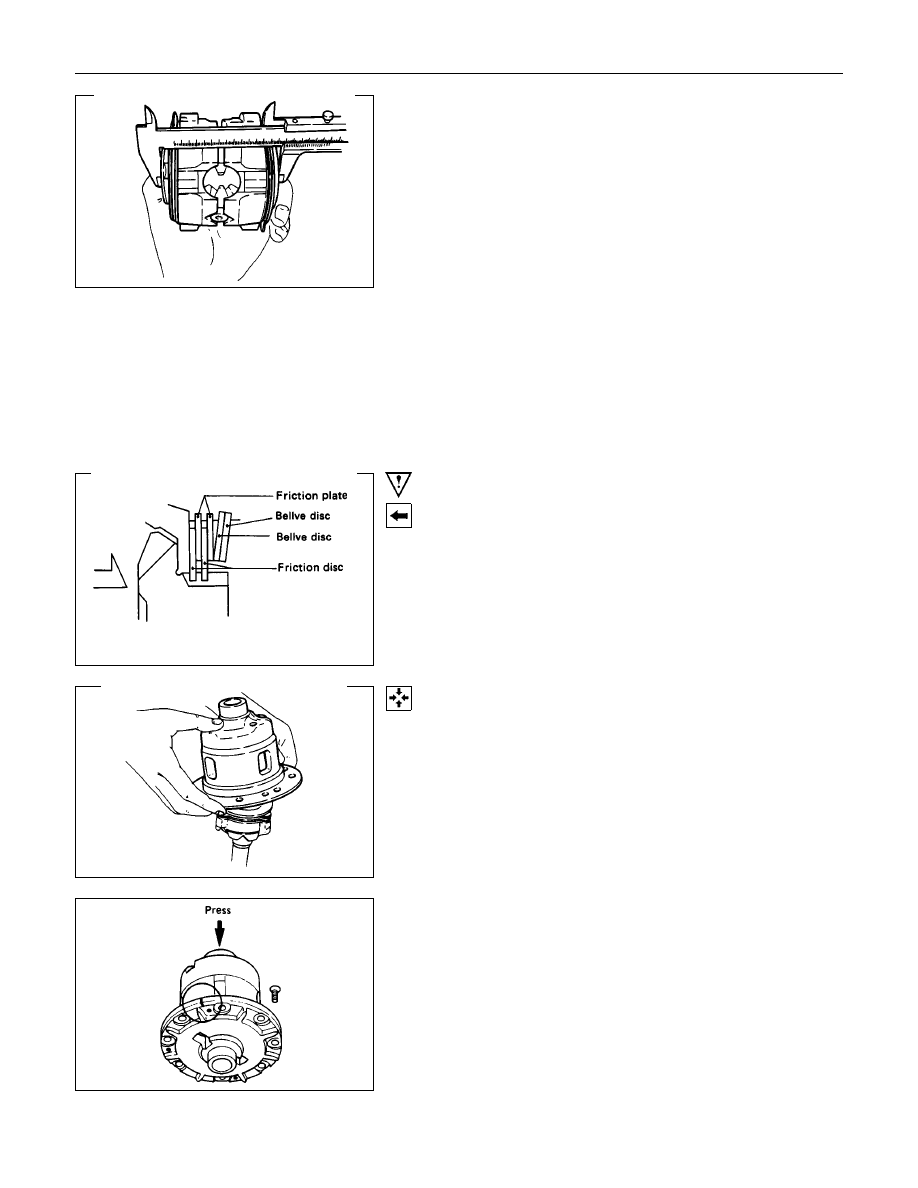
2) Measuring dimension between thrust washers at both ends.
•
Eliminate clearance by pushing pressure ring against the
pinion shaft in axial direction.
•
Eliminate backlash by connecting side gear to the pinion.
•
Measure dimension between thrust washers at both
ends. (H)
3) After each dimension is measured, perform adjustment with
the following procedure.
Adjust so that ((F-B) + G-H) = 0.05 to 0.2 mm. Also, select
a proper thrust washer so that the dimension difference
from back face of the pressure ring to thrust washer
(left/right side) does not exceed 0.05 mm.
Thickness : 1.5, 1.6, 1.7 mm
Important Operations
3. 19. Bellve disc
4. 18. Bellve disc
Install the Bellve disc with dished side turned to the differential
cage side.
9. Pressure Ring
1) Fit two side gears in two pressure rings, one from under a
ring and the other from above a ring.
2) Fit two pairs of a friction disc and a friction plate under it on
and under these two pressure rings. Also, fit disc springs
and plate springs for the discs and plates.
23.Bolt
Align the setting marks on the box and box cover and install
the bolts using the press.

4B-38 REAR AXLE
Confirmation of Operation
•
Using the side gear holder, measure the starting torque of
the side gear.
Starting torque
N
⋅
m (kgf
⋅
m/lb
⋅
ft)
64 - 147 (6.5 - 15/47-108)

REAR AXLE 4B-39
DIFFERENTIAL ASSEMBLY (STD)
Reassembly Steps
1. Differential cage
2. Thrust washer
3. Side gear
▲
4. Pinion gear
5. Thrust block
▲
6. Cross pin
▲
7. Lock pin
▲
8. Ring gear

4B-40 REAR AXLE
Important Operations
4. Pinion Gear
Install the pinion gear by engaging it with the side gears while
turning both pinion gears simultaneously in the same direction.
6. Cross Pin
(1) Be sure to install the cross pin so that it is in alignment with
the lock pin hole in the differential cage.
(2) Backlash between the side gear and the pinion gear.
Backlash
mm(in)
194 mm
0.03 - 0.08 (0.001 - 0.003)
220 mm
0.13 - 0.18 (0.005 - 0.007)
If the backlash is beyond the limits, adjust with a thrust washer
of selected thickness.
Thicknesses of thrust washers available.
mm(in)
194 mm
1.00
(0.039)
1.05
(0.041)
1.10
(0.043)
220 mm
0.80
(0.031)
0.90
(0.035)
1.00
(0.039)
1.10
(0.043)
1.20
(0.047)
1.30
(0.051)
7. Lock Pin
After lock pin installation, stake the cage to prevent the lock pin
from falling out.
Нет комментариевНе стесняйтесь поделиться с нами вашим ценным мнением.
Текст