Isuzu D-Max / Isuzu Rodeo (TFR/TFS). Manual — part 949
REAR AXLE 4B-33
Important Operations
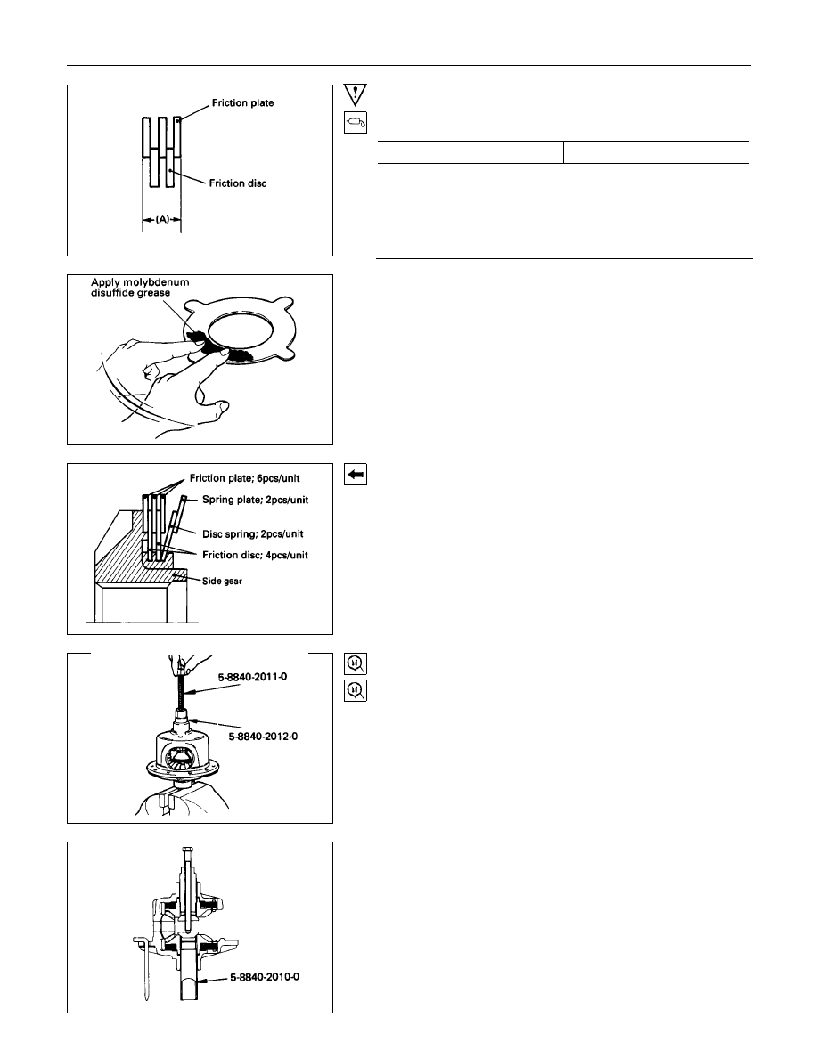
1. Friction disc and plate
Measure the thickness of disc and plate pack (A).
mm(in)
Thickness (A)
7
±
0.1 (0.27
±
0.004)
If the thickness (A) is beyond the limits, adjust with a friction
disc of selected thickness.
Thickness of friction discs available
mm(in)
1.4 (0.055), 1.5 (0.059)
Apply molybdenum disuffide grease to the friction discs and
plates.
3. Spring plate
Install the spring plate with dished side turned side turned to
the differential cage side.
10.Pinion gear
11.Pinion washer
(1) Clamp special tool (side gear holder) into a vise. Set the
LSD assembly.
Holder : 5-8840-2010-0
(J-36563)
(2) Set special tools (side pinion expanders and side pinion
rotator) to the LSD.
Expander : 5-8840-2011-0
(J-36564)
Rotator : 5-8840-2012-0
(J-36565)
4B-34 REAR AXLE
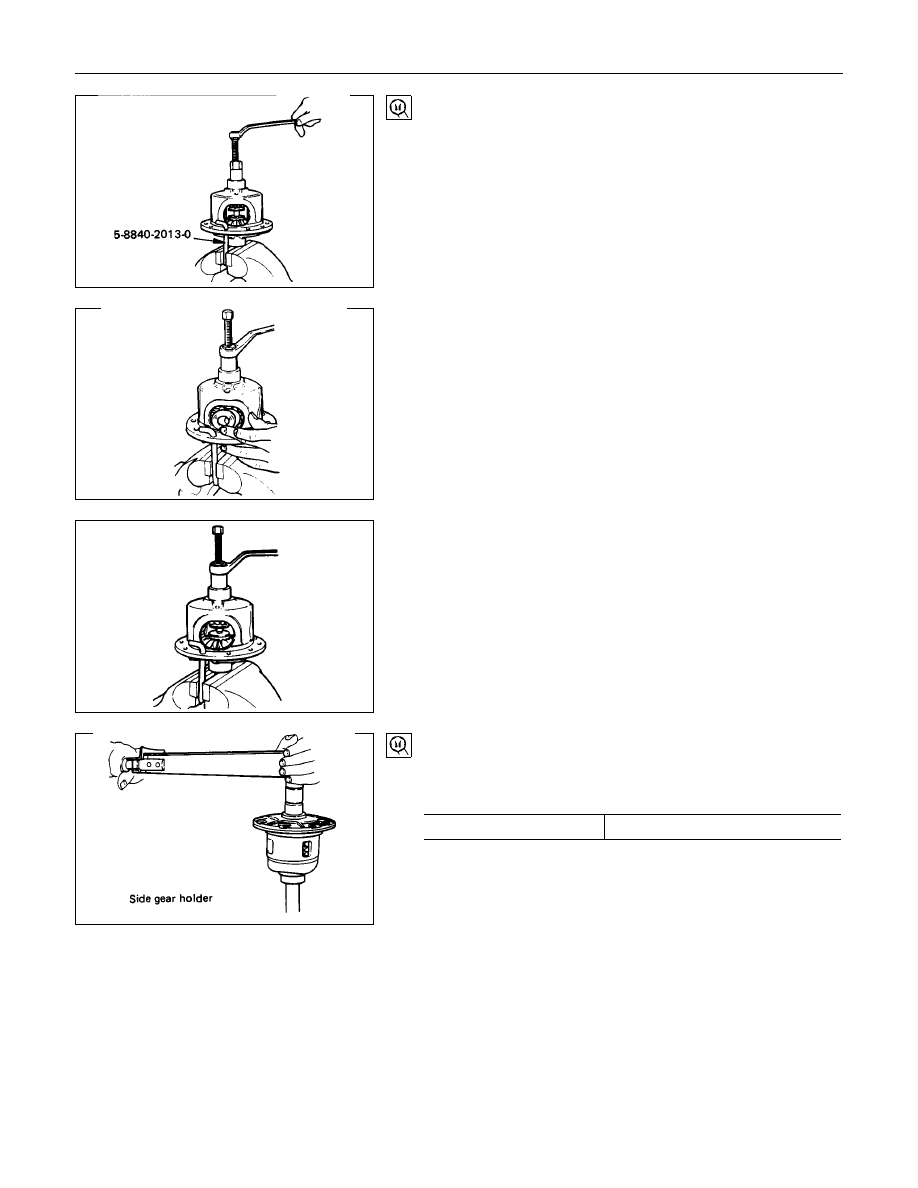
(3) Set special tool (cage lock bar) through a ring gear fixing
hole to a vice.
Then rotate side pinion expanders with a wrench one half to
one full turn to provide proper clearance to install the pinion
gears.
Bar : 5-8840-2013-0
(J-36566)
(4) Attach the pinion gears and washers in the proper order to
the left and right hand side of the differential cage.
(5) With a wrench, turn special tool (pinion rotator) to align the
pinion gear and washer holes with the pinion shaft holes on
the differential cage.
Confirmation of operation
Using the side gear holder, measure the starting of the side
gear.
Starting Torque
N
⋅
m (kgf
⋅
m/lb
⋅
ft)
Standard
147-225 (15 - 23/108 - 166)
Side gear holder : 5-8840-2010-0
(J-36563)
Side gear rotor : 5-8840-2012-0
(J-36565)
REAR AXLE 4B-35
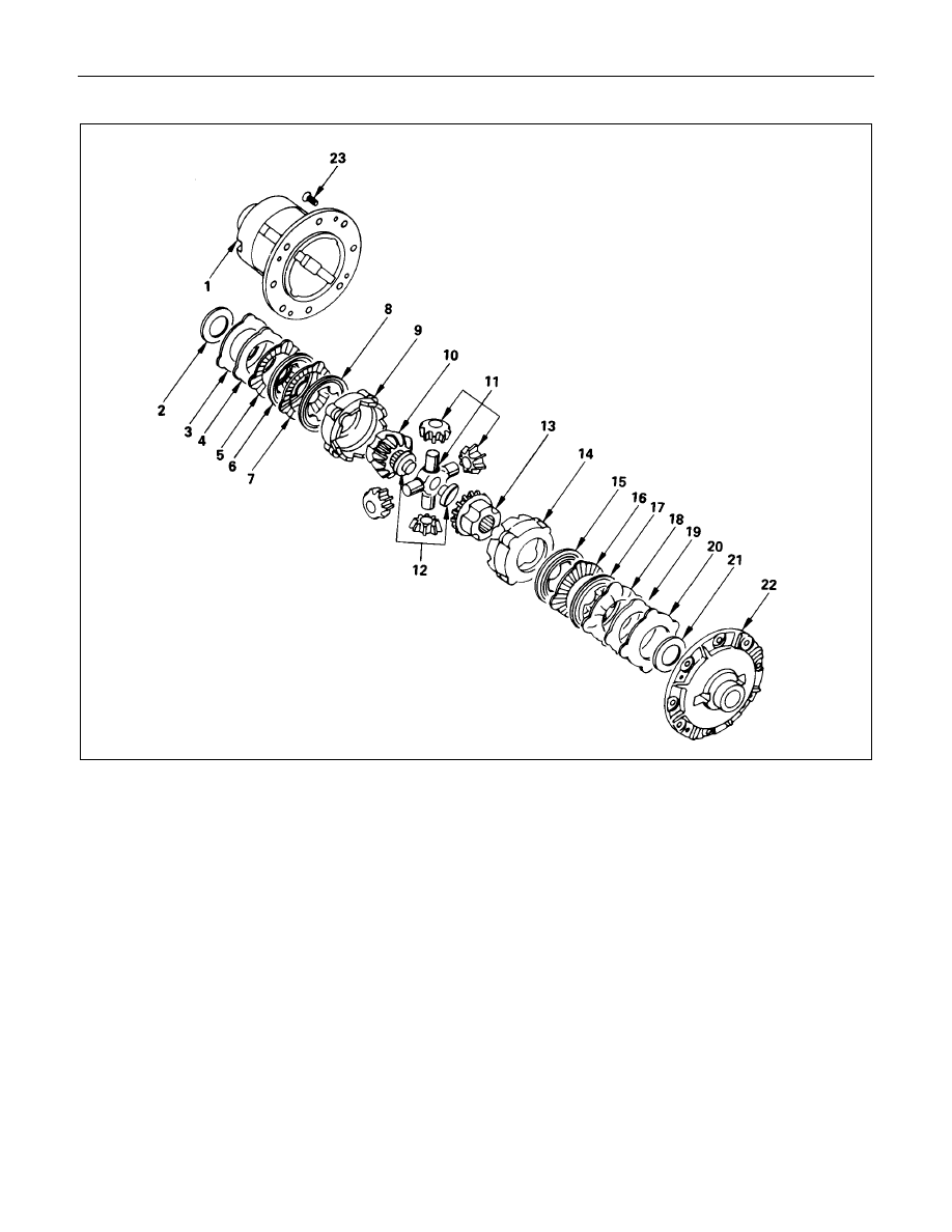
<FOR RING SIZE 220 mm>
Reassembly Steps
1. Differential cage
2. Thrust washer
▲
3. Bellve disc
▲
4. Bellve disc
5. Friction plate
6. Friction disc
7. Friction plate
8. Friction disc
▲
9. Pressure ring
10. Side gear
11. Pinion gear and pinion spider
12. Thrust block
13. Side gear
14. Pressure ring
15. Friction disc
16. Friction plate
17. Friction disc
18. Friction plate
▲
19. Bellve disc
▲
20. Bellve disc
21. Thrust washer
22. Differential cage cover
▲
23. Bolt
4B-36 REAR AXLE
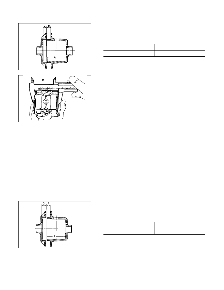
Adjustment of Clearance between
Friction Disc and Plate
1) Measuring depth of differential case
mm(in)
Standard (A-B)
80.58 (3.17)
(C)
10.58 (0.41)
2) Measuring overall length of pressure ring, friction disc and
plate assembly
•
Assembly pinion shaft with pressure ring, then friction
disc and plate.
•
Measure length between plates at both ends over V-
shape groove. (D)
3) After A, B, C and D dimensions are measured, perform
adjustment with the following procedure.
•
Measure disc spring :
1.75 mm (0.69 in)
×
2 pcs (E)
•
Measure thickness of plate spring
Standard dimension :
1.75 mm (0.069 in)
×
2 pcs (F)
4) Select a friction disc or plate so that ((A-B+C) - (D+E+F) =
0.06 to 0.20 mm (0.002 to 0.008 in.) and also the difference
in total dimension of friction disc and plate, plate spring and
disc spring (left/right side) does not exceed 0.05 mm (0.002
in.).
Thickness : 1.75, 1.85 mm
Adjusting Backlash of Side Gear in Axial
Direction
1) Measuring depth of differential case
mm(in.)
Standard (F-B)
82.03 (3.23)
(G)
12.03 (0.47)
Нет комментариевНе стесняйтесь поделиться с нами вашим ценным мнением.
Текст