Isuzu D-Max / Isuzu Rodeo (TFR/TFS). Manual — part 1039

CLUTCH 7C-15
CLUTCH
REMOVAL AND INSTALLATION
HEC Engine Series
4J Engine Series
6VD1
Removal Steps
1. Transmission assembly
▲
2. Pressure Plate assembly
▲
3. Driven plate assembly
4. Release bearing
5. Shift fork
6. Flywheel assembly and cran bearing
(HEC Engine Series)
7. Fulcrum bridge (6VD1)
Installation Steps
To install, follow the removal steps in the
reverse order.

7C-16 CLUTCH
Important Operations - Removal
1. Transmission Assembly
Refer to “MANUAL TRANSMISSION” of section 7B and 7B1
for “REMOVAL AND INSTALLATION” procedure.
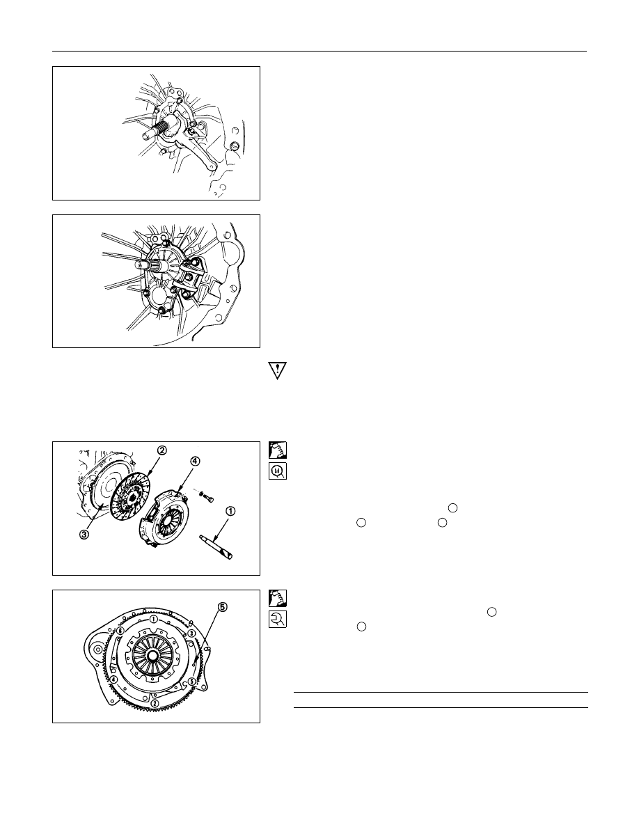
2. Clutch Pressure Plate Assembly (HEC Engine Series)
3. Driven Plate Assembly (HEC Engine Series)
(1) Use the clutch pilot aligner
1
to prevent the driven plate
assembly
2
from falling free.
Clutch Pilot Aligner : 5-8840-2634-0
(2) Loosen the clutch cover bolts in the numerical order shown
in the illustration.
(3) Remove the pressure plate assembly
3
from the flywheel.
(4) Remove the driven plate from the flywheel.
3. Driven Plate Assembly (Except HEC Engine Series)
(1) Use the pilot aligner to prevent the driven plate assembly
from falling free.
Pilot aligner: 5-8525-3001-0 (J-24547)
(2) Mark the flywheel, clutch cover and pressure plate lug for
alignment when installing.
6VD1
4. Release Bearing (6VD1)
Remove the release bearing from the transmission case.
CLUTCH 7C-17
6VD1
5. Shift Fork (6VD1)
(1) Remove the snap pin.
(2) Remove the shift fork pin and shift fork from the fulcrum
bridge.
6VD1
7. Fulcrum Bridge (6VD1)
(1) Remove the fulcrum bridge bolts.
(2) Remove the fulcrum bridge from the transmission case.
Important Operations - Installation
Follow the removal procedure in reverse order to perform the
installation procedure.
Pay careful attention to the important points during the
installation procedure.
3. Driven plate Assembly (HEC Engine Series)
2. Clutch Pressure Plate Assembly (HEC Engine Series)
(1) Clean the flywheel surface.
(2) Clean the facing surface.
(3) Use the clutch pilot aligner
1
to install the driven plate
assembly
2
to the flywheel
3
.
Clutch Pilot Aligner : 5-8840-2634-0
(4) Clean the pressure plate surfaces.
(5) Align the pressure plate assembly
4
with the flywheel
knock pin
5
.
(6) Install the pressure plate assembly to the flywheel.
(7) Tighten the clutch cover bolts a little at a time in the
numerical order shown in the illustration.
Clutch Cover Bolt Torque
N
⋅
m (kgf
⋅
m/lb
⋅
ft)
17.6
±
4.9 (1.8
±
0.5/13.0
±
3.6)

7C-18 CLUTCH
8. Remove the clutch pilot aligner.
Note:
Do not strike the clutch pilot aligner with a hammer to
remove it.
6VD1
7. Fulcrum Bridge (6VD1)
(1) Install the fulcrum bridge to the transmission case.
(2) Tighten three fulcrum bridge bolts to the specified torque.
Fulcrum Bridge Bolt Torque
N
⋅
m (kg
⋅
m/lb
⋅
ft)
39 (3.9/28)
6VD1
5. Shift Fork (6VD1)
(1) Apply molybdenum disulfide contained type grease to the
pin hole inner circumferences and thrust surfaces.
(2) Attach the shift fork to the fulcrum bridge and insert the pin
from below of the fulcrum bridge.
(3) Install the washer and snap pin.
6VD1
4. Release Bearing (6VD1)
(1) Apply molybdenum disulfide contained type grease to the
areas shown in illustration.
Нет комментариевНе стесняйтесь поделиться с нами вашим ценным мнением.
Текст