Isuzu D-Max / Isuzu Rodeo (TFR/TFS). Manual — part 47

4JA1-TC/4JH1-TC ENGINE DRIVEABILITY AND EMISSIONS
6E–183
8
Using the DVM and check the EGR EVRV circuit.
Breaker box is available:
1. Ignition “Off”, engine “Off”.
2. Install the breaker box as type A. (ECM
disconnected) Ref. Page 6E-81
3. Remove the EGR EVRV connector.
4. Check the circuit for open or short to ground
circuit.
Was the problem found?
Breaker box is not available:
1. Ignition “Off”, engine “Off”.
2. Disconnect the ECM connector.
3. Remove the EGR EVRV connector.
4. Check the circuit for open or short to ground
circuit.
Was the problem found?
—
Repair faulty
harness and
verify repair
Go to Step 11
9
Substitute a known good EGR EVRV and recheck.
Was the problem solved?
—
Go to Step 10
Go to Step 11
10
Replace the EGR EVRV.
Is the action complete?
—
Verify repair
—
11
Is the ECM programmed with the latest software
release?
If not, download the latest software to the ECM using
the “SPS (Service Programming System)”.
Was the problem solved?
—
Verify repair
Go to Step 12
12
Replace the ECM.
Is the action complete?
IMPORTANT: The replacement ECM must be
programmed. Refer to section of the Service
Programming System (SPS) in this manual.
Following ECM programming, the immobiliser system
(if equipped) must be linked to the ECM. Refer to
section 11 “Immobiliser System-ECM replacement” for
the ECM/Immobiliser linking procedure.
—
Verify repair
—
Step
Action
Value(s)
Yes
No
97
2
C-52
97
2
C-52
C-57

6E–184
4JA1-TC/4JH1-TC ENGINE DRIVEABILITY AND EMISSIONS
Diagnostic Trouble Code (DTC) P0400 (Symptom Code 5) (Flash Code 32)
Exhaust Gas Recirculation Flow Insufficient Detected
Step
Action
Value(s)
Yes
No
1
Was the “On-Board Diagnostic (OBD) System Check”
performed?
—
Go to Step 2
Go to On Board
Diagnostic
(OBD) System
Check
2
1. Connect the Tech 2.
2. Review and record the failure information.
3. Select “F0: Read DTC Infor As Stored By ECU” in
“F0: Diagnostic Trouble Codes”.
Is the DTC P0400 (Symptom Code 5) stored as
“Present Failure”?
—
Go to Step 3
Refer to
Diagnostic Aids
and Go to Step
3
3
1. Using the Tech 2, ignition “On” and engine “Off”.
2. Select “F1: Clear DTC Information” in “F0:
Diagnostic Trouble Codes” with the Tech 2 and
clear the DTC information.
3. Operate the vehicle and monitor the “F0: Read
DTC Infor As Stored By ECU” in the “F0:
Diagnostic Trouble Codes”.
Was the DTC P0400 (Symptom Code 5) stored in this
ignition cycle?
—
Go to Step 4
Refer to
Diagnostic Aids
and Go to Step
4
4
Visually check the EGR control vacuum hose.
If the hose is clogged or disconnected, repair as
necessary.
Was the problem found?
—
Verify repair
Go to Step 5
5
Using the DVM and check the EGR EVRV.
1. Ignition “Off”, engine “Off”.
2. Disconnect the EGR EVRV connector.
3. Measure the resistance of EGR EVRV solenoid
coil.
Does the tester indicate standard resistance?
Approximately
14
Ω at 20°C
Go to Step 8
Go to Step 6
6
Substitute a known good EGR EVRV and recheck.
Was the problem solved?
—
Go to Step 7
Go to Step 8
7
Replace the EGR EVRV.
Is the action complete?
—
Verify repair
—
1
2
EGR EVRV
1
2
4JA1-TC/4JH1-TC ENGINE DRIVEABILITY AND EMISSIONS
6E–185
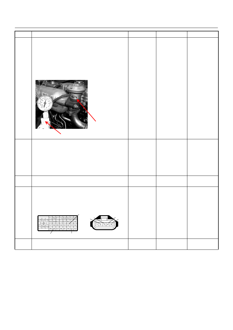
8
Using the vacuum pump and check the EGR valve
operation for the following condition through the small
window.
• Restrict shaft movement. Check for objects sticking
the shaft, broken diaphragm or excessive carbon
deposit.
If a problem is found, repair as necessary.
Was a problem found?
—
Verify repair or
Go to Step 10
Go to Step 9
9
Inspect the EGR valve.
1. Remove the EGR valve from the engine.
2. Inspect the EGR valve whether pintle valve is
stuck or damaged.
If excessive carbon deposit is found, clean up the
EGR valve and inspect damage of the pintle and seat.
Was the problem found?
—
Verify repair or
Go to Step 10
Go to Step 11
10
Replace the EGR valve.
Is the action complete?
—
Verify repair
-
11
Check for poor/faulty connection at the MAF sensor or
ECM connector. If a poor/faulty connection is found,
repair as necessary.
Was the problem found?
—
Verify repair
Go to Step 12
12
Visually check the MAF sensor.
Was the problem found?
—
Go to Step 14
Go to Step 13
Step
Action
Value(s)
Yes
No
Vacuum Pump
Small Window
92
88
83
2 3
4
5
C-51
C-57(B)
6E–186
4JA1-TC/4JH1-TC ENGINE DRIVEABILITY AND EMISSIONS
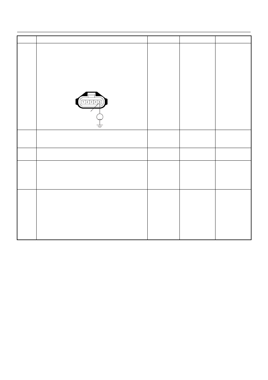
13
Using the DVM and check the MAF sensor signal
circuit.
1. Ignition “On”, engine “Off”.
2. Disconnect the MAF sensor connector.
3. Check the circuit for short to power supply circuit.
Was the DVM indicated specified value?
Less than 1V
Go to Step 16
Repair faulty
harness and
verify repair
14
Substitute a known good MAF & IAT sensor assembly
and recheck.
Was the problem solved?
—
Go to Step 15
Go to Step 16
15
Replace the MAF & IAT sensor assembly.
Is the action complete?
—
Verify repair
—
16
Is the ECM programmed with the latest software
release?
If not, download the latest software to the ECM using
the “SPS (Service Programming System)”.
Was the problem solved?
—
Verify repair
Go to Step 17
17
Replace the ECM.
Is the action complete?
IMPORTANT: The replacement ECM must be
programmed. Refer to section of the Service
Programming System (SPS) in this manual.
Following ECM programming, the immobiliser system
(if equipped) must be linked to the ECM. Refer to
section 11 “Immobiliser System-ECM replacement” for
the ECM/Immobiliser linking procedure.
—
Verify repair
—
Step
Action
Value(s)
Yes
No
5
V
C-51
Нет комментариевНе стесняйтесь поделиться с нами вашим ценным мнением.
Текст