Isuzu D-Max / Isuzu Rodeo (TFR/TFS). Manual — part 48
4JA1-TC/4JH1-TC ENGINE DRIVEABILITY AND EMISSIONS
6E–187
Diagnostic Trouble Code (DTC) P0400 (Symptom Code 8) (Flash Code 32)
Exhaust Gas Recirculation Circuit Short to Battery
Step
Action
Value(s)
Yes
No
1
Was the “On-Board Diagnostic (OBD) System Check”
performed?
—
Go to Step 2
Go to On Board
Diagnostic
(OBD) System
Check
2
1. Connect the Tech 2.
2. Review and record the failure information.
3. Select “F0: Read DTC Infor As Stored By ECU” in
“F0: Diagnostic Trouble Codes”.
Is the DTC P0400 (Symptom Code 8) stored as
“Present Failure”?
—
Go to Step 3
Refer to
Diagnostic Aids
and Go to Step
3
3
1. Using the Tech 2, ignition “On” and engine “Off”.
2. Select “F1: Clear DTC Information” in “F0:
Diagnostic Trouble Codes” with the Tech 2 and
clear the DTC information.
3. Operate the vehicle and monitor the “F0: Read
DTC Infor As Stored By ECU” in the “F0:
Diagnostic Trouble Codes”.
Was the DTC P0400 (Symptom Code 8) stored in this
ignition cycle?
—
Go to Step 4
Refer to
Diagnostic Aids
4
Check for poor/faulty connection at the EGR EVRV or
ECM connector. If a poor/faulty connection is found,
repair as necessary.
Was the problem found?
—
Verify repair
Go to Step 5
5
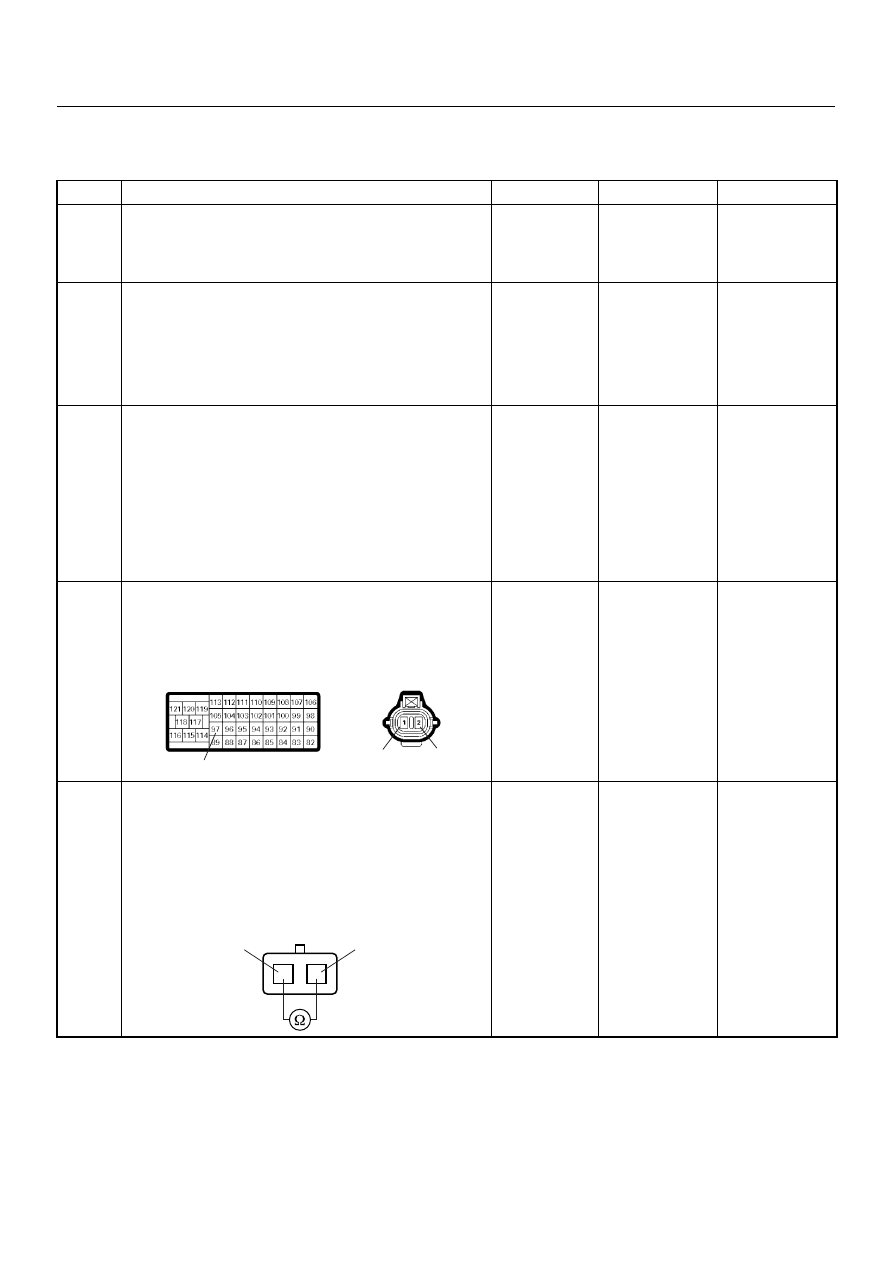
Using the DVM and check the EGR EVRV.
1. Ignition “Off”, engine “Off”.
2. Disconnect the EGR EVRV connector.
3. Measure the resistance of EGR EVRV solenoid
coil.
Does the tester indicate standard resistance?
Approximately
14
Ω at 20°C
Go to Step 6
Go to Step 8
97
1
2
C-52
C-57
1
2
EGR EVRV
1
2

6E–188
4JA1-TC/4JH1-TC ENGINE DRIVEABILITY AND EMISSIONS
6
Using the DVM and check the EGR EVRV circuit.
1. Ignition “Off”, engine “Off”.
2. Remove the EGR EVRV connector and ECM
connector.
3. 3. Check the circuit for short to voltage circuit.
Was the DVM indicated specified value?
No continuity
Go to Step 10
Go to Step 7
7
Repair the short to voltage circuit.
Is the action complete?
—
Verify repair
—
8
Substitute a known good EGR EVRV and recheck.
Was the problem solved?
—
Go to Step 9
Go to Step 10
9
Replace the EGR EVRV.
Is the action complete?
—
Verify repair
—
10
Is the ECM programmed with the latest software
release?
If not, download the latest software to the ECM using
the “SPS (Service Programming System)”.
Was the problem solved?
—
Verify repair
Go to Step 11
11
Replace the ECM.
Is the action complete?
IMPORTANT: The replacement ECM must be
programmed. Refer to section of the Service
Programming System (SPS) in this manual.
Following ECM programming, the immobiliser system
(if equipped) must be linked to the ECM. Refer to
section 11 “Immobiliser System-ECM replacement” for
the ECM/Immobiliser linking procedure.
—
Verify repair
—
Step
Action
Value(s)
Yes
No
1
2
C-52
4JA1-TC/4JH1-TC ENGINE DRIVEABILITY AND EMISSIONS
6E–189
DIAGNOSTIC TROUBLE CODE (DTC) P0500 (SYMPTOM CODE 1)
(FLASH CODE 24) VEHICLE SPEED SENSOR CIRCUIT HIGH INPUT
DIAGNOSTIC TROUBLE CODE (DTC) P0500 (SYMPTOM CODE A)
(FLASH CODE 24) VEHICLE SPEED SENSOR INPUT SIGNAL FREQUENCY
TOO HIGH
DIAGNOSTIC TROUBLE CODE (DTC) P0500 (SYMPTOM CODE B)
(FLASH CODE 24) VEHICLE SPEED SENSOR INCORRECT SIGNAL
Ignition
SW
Meter
15A
6 15
7
Batt
Batt
0.5
RED/
WHT
29
0.5
ORG/
BLU
43
0.5
BRN/
YEL
42
0.5
BLK/
RED
27
0.5
BLU/
WHT
0.5 BLU/BLK
68
0.5
WHT
2.0
BLK
35
VSS
0.85
YEL
Imnobiliser
Control Unit
7
8
0.5
BRN/
YEL
IC
0.85
YEL
Glow
Check
Engine
Tacho
Meter
Speed
Meter
A/T
TCM
µP
µP
µP
µP
Engine
Control
Module
(ECM)

6E–190
4JA1-TC/4JH1-TC ENGINE DRIVEABILITY AND EMISSIONS
Condition for setting the DTC and action taken when the DTC sets
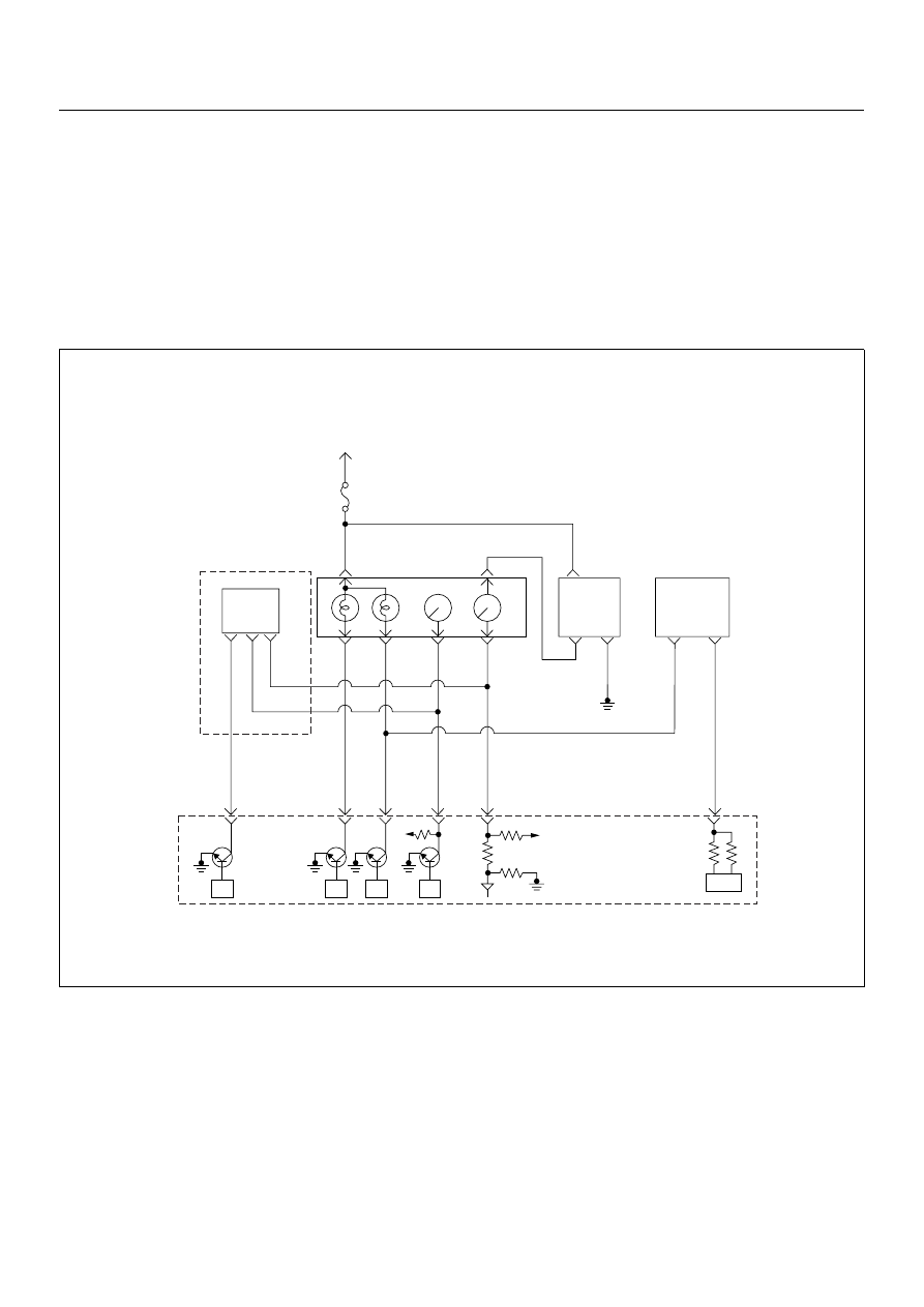
Circuit Description
The VSS is a magnet rotated by the transmission output
shaft. The VSS uses a hall element. It interacts with the
magnetic field treated by the rotating magnet. It outputs
pulse signal. The 12 volts operating supply from the
meter fuse.
The engine control module (ECM) calculates the vehicle
speed by VSS.
Diagnostic Aids
An intermittent may be caused by the following:
• Poor connections.
• Misrouted harness.
• Rubbed through wire insulation.
• Broken wire inside the insulation.
Check for the following conditions:
• Poor connection at ECM-Inspect harness connectors
for backed out terminals, improper mating, broken
locks, improperly formed or damaged terminals, and
poor terminal to wire connection.
• Damaged harness-Inspect the wiring harness for
damage. If the harness appears to be OK, observe
the DTC P0500 display on the Tech2 while moving
connectors and wiring harnesses. A change in the
display will indicate the location of the fault.
Diagnostic Trouble Code (DTC) P0500 (Symptom Code 1) (Flash Code 24)
Vehicle Speed Sensor Circuit High Input
Flash
Code
Code
Symptom
Code
MIL
DTC Name
DTC Setting Condition
Fail-Safe (Back Up)
24
P0500
1
ON
at
next
igni-
tion
cycle
Vehicle Speed Sensor Circuit
High Input
Vehicle speed is more than
200km/h.
ECM uses vehicle speed 5km/
h condition as substitute.
A
ON
at
next
igni-
tion
cycle
Vehicle Speed Sensor Input
Signal Frequency Too High
Input signal frequency is too
high.
ECM uses vehicle speed 5km/
h condition as substitute.
B
ON
at
next
igni-
tion
cycle
Vehicle Speed Sensor Incor-
rect Signal
1. Engine speed is more than
3600rpm.
2. Fuel injection quantity is
more than 41mg/stk.
3. Vehicle speed is below
1.5km/h.
Fuel injection quantity is
reduced.
Step
Action
Value(s)
Yes
No
1
Was the “On-Board Diagnostic (OBD) System Check”
performed?
—
Go to Step 2
Go to On Board
Diagnostic
(OBD) System
Check
2
1. Connect the Tech 2.
2. Review and record the failure information.
3. Select “F0: Read DTC Infor As Stored By ECU” in
“F0: Diagnostic Trouble Codes”.
Is the DTC P0500 (Symptom Code 1) stored as
“Present Failure”?
—
Go to Step 3
Refer to
Diagnostic Aids
and Go to Step
3
Нет комментариевНе стесняйтесь поделиться с нами вашим ценным мнением.
Текст