Isuzu D-Max / Isuzu Rodeo (TFR/TFS). Manual — part 864

6E–185
3.2L ENGINE DRIVEABILITY AND EMISSIONS
DTC P1171 – Fuel System Lean During Acceleration
(Cont'd)
Step
No
Yes
Value(s)
Action
7
1. Ignition “OFF.”
2. Remove the fuel pump relay and replace it with a
fused jumper which will connect the relay’s battery
terminal to the terminal leading to the fuel pump
fuse.
3. While the fuel pump is operating, use pliers to slowly
close the return line (do not exceed the first
specified value).
Using the pliers to restrict the return line, can the fuel
pressure be manipulated to exceed the second
specified value?
414 kpa (60
psi) 325 kpa
(46 psi)
Go to
Diagnostic
Aids
Go to
Step 8
8
Check for:
D
Faulty fuel pump
D
Restricted fuel pump strainer (sock)
D
Incorrect fuel pump
D
Incorrect fuel being used
D
Hot fuel
Is the action complete?
—
Verify repair
—
6E–186 3.2L ENGINE DRIVEABILITY AND EMISSIONS
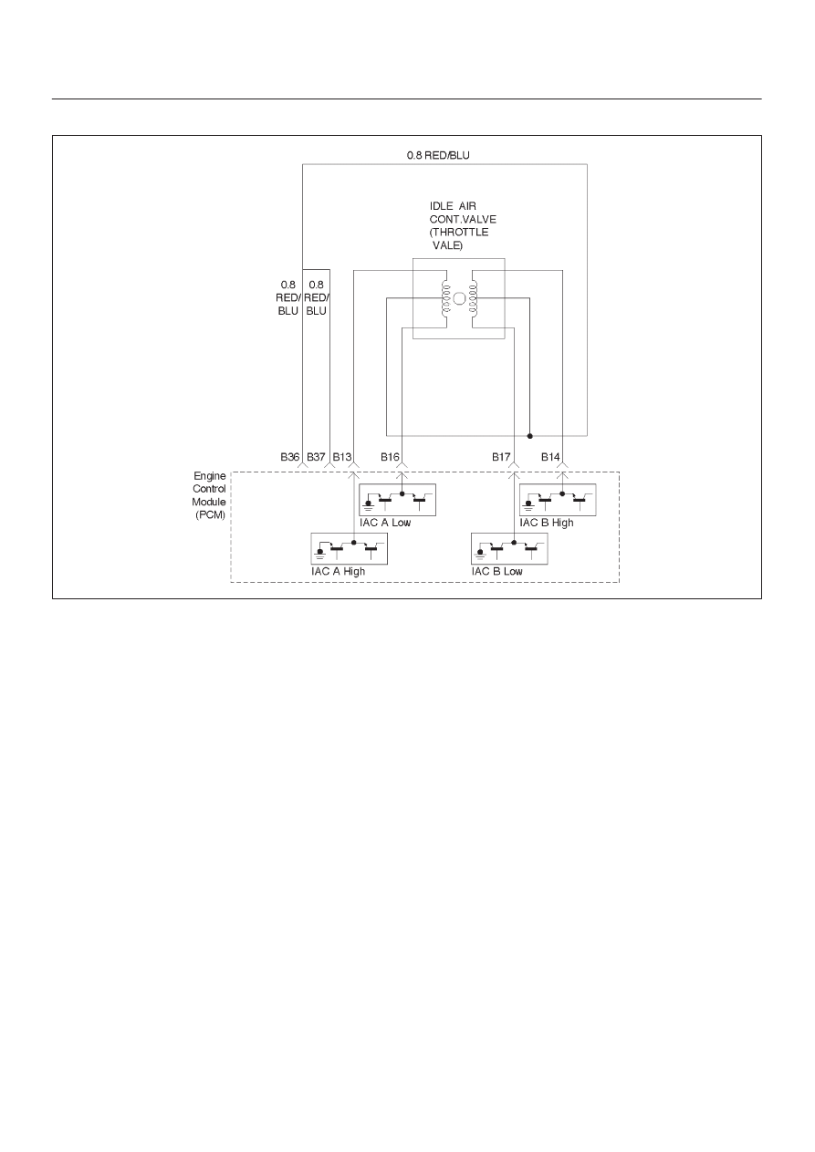
Diagnostic Trouble Code (DTC) P1508 (Flash DTC=22) IAC System Low RPM
060RW076
Circuit Description
The engine control module (ECM) controls engine idle
speed by adjusting the position of the idle air control (IAC)
motor pintle. The IAC is a bi-directional stepper motor
driven by two coils. The ECM applies current to the IAC
coils in steps (counts) to extend the IAC pintle into a
passage in the throttle body to decrease air flow. The
ECM reverses the current to retract the pintle, increasing
air flow. This method allows highly accurate control of idle
speed and quick response to changes in engine load. If
the ECM detects a condition where too low of an idle
speed is present and the ECM is unable to adjust idle
speed by increasing the IAC counts, DTC P1508 will set,
indicating a problem with the idle control system.
Conditions for Setting the DTC
D
No Tech 2 test is being run.
D
None of these DTCs are set: TP sensor, CMP, CKP,
MAF.
D
Barometric pressure is above 75 kpa.
D
Engine coolant temperature (ECT) is above 75
°
C.
D
Ignition voltage is above 11 volts.
D
The throttle is closed.
D
Engine speed is between 1000 RPM and 6000 RPM.
D
Relation of IAC step and MAF in wrong.
D
All of the above conditions are met for 1 seconds.
Action Taken When the DTC Sets
D
The ECM will illuminate the malfunction indicator lamp
(MIL) after the second consecutive trip in which the
fault is detected.
D
The ECM will store conditions which were present
when the DTC was set as Freeze Frame and in the
Failure Records data.
Conditions for Clearing the MIL/DTC
D
The ECM will turn the MIL “OFF” on the third
consecutive trip cycle during which the diagnostic has
been run and the fault condition is no longer present.
D
A history DTC P1508 will clear after 40 consecutive
warm-up cycles have occurred without a fault.
D
DTC P1508 can be cleared by using the Tech 2 “Clear
Info” function or by disconnecting the ECM battery
feed.
Diagnostic Aids
Check for the following conditions:
D
Poor connection at ECM or IAC motor – Inspect
harness connectors for backed-out terminals,
improper mating, broken locks, improperly formed or
damaged terminals, and poor terminal-to-wire
connection.
D
Damaged harness – Inspect the wiring for damage.
D
Restricted air intake system – Check for a possible
collapsed air intake duct, restricted air filter element,
or foreign objects blocking the air intake system.

6E–187
3.2L ENGINE DRIVEABILITY AND EMISSIONS
D
Throttle body – Check for objects blocking the IAC
passage or throttle bore, excessive deposits in the IAC
passage and on the IAC pintle, and excessive deposits
in the throttle bore and on the throttle plate.
D
Large vacuum leak – Check for a condition that causes
a large vacuum leak, such as an incorrectly installed or
faulty PCV valve or a disconnected brake booster
hose.
Reviewing the Failure Records vehicle mileage since the
diagnostic test last failed may help determine how often
the condition that caused the DTC to be set occurs. This
may assist in diagnosing the condition.
DTC P1508 –IAC System Low RPM
Step
Action
Value(s)
Yes
No
1
Was the “On-Board Diagnostic (OBD) System Check”
performed?
—
Go to
Step 2
Go to
OBD
System
Check
2
1. Start the engine.
2. Turn all accessories “OFF”(A/C, rear defroster,
etc).
3. Using a Tech 2, command RPM up to 1500, down to
500, and the up to 1500 while monitoring the
“Engine Speed” on the Tech 2.
NOTE: This Tech 2 command may cause the engine to
“cut out” when RPM goes above 1500. If this occurs,
the “cutting out” will stop when the Tech 2 command for
the test is discontinued, or if the Tech 2 command is
changed to less than 1500 RPM.
Does the “Engine Speed” remain within the specified
value of the “Desired Idle” for each RPM command?
±
50 RPM
No trouble
found. Go to
Diagnostic
Aids
Go to
Step 3
3
1. Disconnect the IAC.
2. Install IAC Node Light J 37027 or equivalent.
3. With the engine running, command RPM up to
1500, down to 500, and then up to 1500 while
observing the node light.
NOTE: This Tech 2 command may cause the engine to
“cut out” when RPM goes above 1500. If this occurs,
the “cutting out” will stop when the Tech 2 command for
the test is discontinued, or if the Tech 2 command is
changed to less than 1500 RPM.
Does each node light cycle red and green (never
“OFF”)?
—
Go to
Step 5
Go to
Step 4
4
1. Check the following circuits for an open, short to
voltage, short ground, or poor connections at the
ECM:
D
IAC “A” Low.
D
IAC “A” High.
D
IAC “B” Low.
D
IAC “B” High.
2. If a problem its found, repair as necessary,
Was a problem found?
—
Verify repair
Go to
Step 8

6E–188 3.2L ENGINE DRIVEABILITY AND EMISSIONS
DTC P1508 –IAC System Low RPM
(Cont'd)
Step
No
Yes
Value(s)
Action
5
Visually/physically inspect for following conditions:
D
Restricted air intake system. Check for a possible
collapsed air intake duct, restricted air filter
element, or foreign objects blocking the air intake
system.
D
Throttle body. Check for objects blocking the IAC
passage or throttle bore, excessive deposits in
the IAC passage and on the IAC pintle, and
excessive deposits in the throttle bore and on the
throttle plate.
Do any of the above require a repair?
—
Refer to
appropriate
section for
on-vehicle
service
Go to
Step 6
6
1. Check for a poor connection at the IAC harness
connector.
2. If a problem is found, replace faulty terminals as
necessary.
Was a problem found?
—
Verify repair
Go to
Step 7
7
Replace the IAC valve.
Is the action complete?
—
Verify repair
—
8
Replace the ECM.
Is the action complete?
—
Verify repair
—
Нет комментариевНе стесняйтесь поделиться с нами вашим ценным мнением.
Текст