Isuzu Rodeo UE. Manual — part 507
7B–60
MANUAL TRANSMISSION
226RS048
226RS049
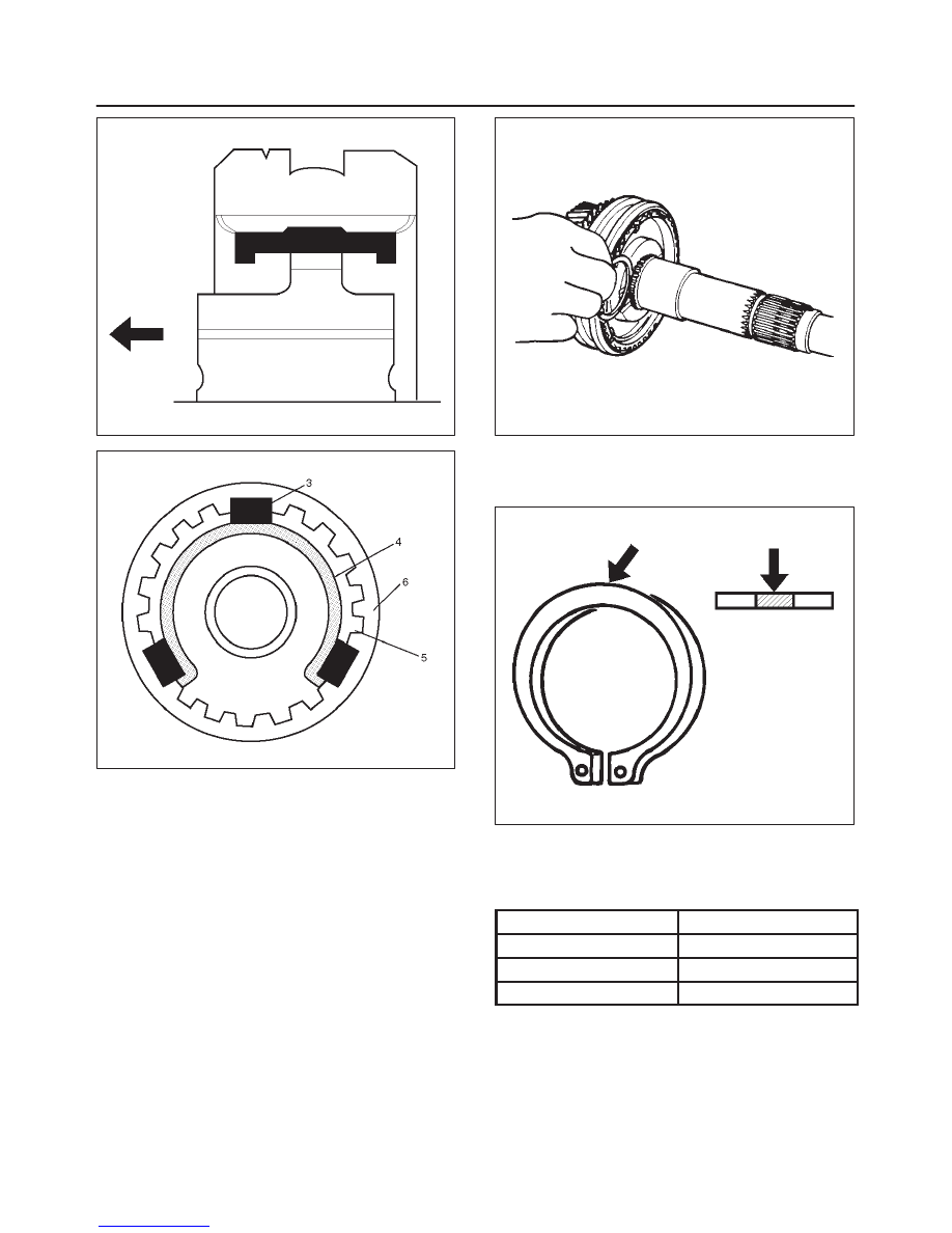
7. Install clutch hub snap ring(19) by performing the
following steps:
f
Select the snap ring which will provide the minimum
clearance between the 1st–2nd clutch hub and the
snap ring.
226RS050
There are three snap ring sizes available.
The snap rings are color coded to indicate their
thickness.
226RS021
Clutch Hub and Snap Ring Clearance
Standard: 0 – 0.1 mm (0 – 0.004 in)
Snap Ring Availability
Thickness
Color Coding
1.80 mm (0.071 in)
White
1.85 mm (0.073 in)
Yellow
1.90 mm (0.075 in)
Blue
f
Use a pair of snap ring pliers to install the snap ring
to the mainshaft.
The snap ring must be fully inserted into the
mainshaft snap ring groove.
MANUAL TRANSMISSION
7B–61
226RS031
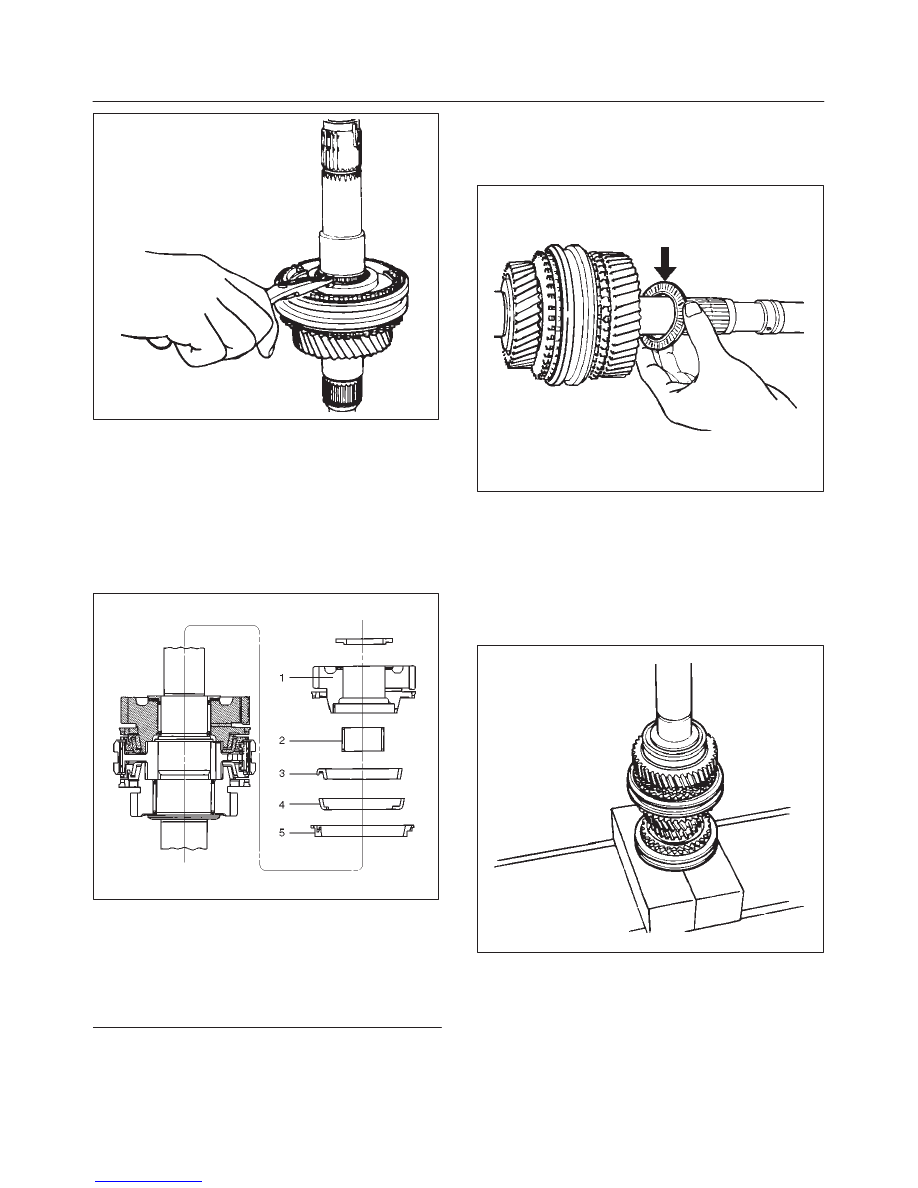
8. Install needle bearing(18), 1st block ring(17), 1st
outside ring(16), 1st inside ring(15), and 1st gear(14).
f
Apply engine oil to the needle bearing, 1st gear
thrust surfaces and synchronizer ring friction
surfaces.
f
Install the needle bearing and the 1st gear to the
mainshaft.
The 1st gear dog teeth must be facing the
transmission front side.
226RS053
Legend
(1) 1st Gear
(2) Needle Bearing
(3) Inside Ring
(4) Outside Ring
(5) Block Ring
9. Install the 1st gear thrust bearing and the race(13) to
the main shaft.
The thrust bearing side must be facing the
transmission front side.
226RS054
10. Apply engine oil to the mainshaft ball bearing(12) and
the mainshaft(26).
Install the ball bearing(12) and needle bearing
collar(11) to the mainshaft(26).
The ball bearing snap ring groove must be facing the
transmission rear side.
Use a bench press and installer J–6133–01 to slowly
force the collar into place.
226RS055
7B–62
MANUAL TRANSMISSION
11. Apply engine oil to the needle bearing and the 3rd
gear thrust surfaces.
Install the needle bearing(10) and the 3rd gear(9) to
the mainshaft.
The 3rd gear dog teeth must be facing the
transmission front side.
226RS056
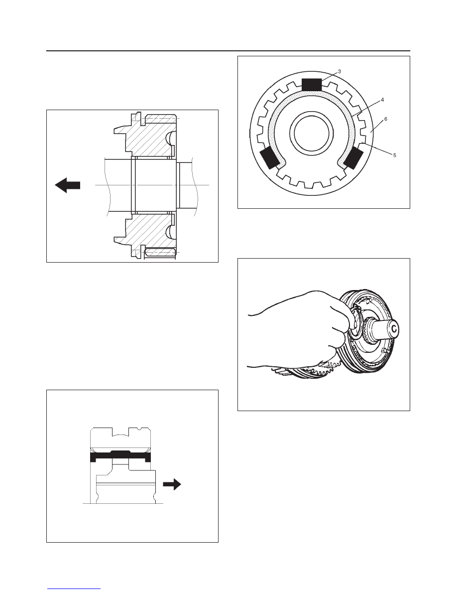
12. Install 3rd block ring(8).
13. Check and install 3rd–4th synchronizer assembly(7)
by the following steps:
1. Check that the inserts(3) fit snugly into the block
ring insert grooves.
2. Check that the insert springs(4) are fitted to the
inserts as shown in the illustration.
3. Check that the clutch hub(5) and the sleeve(6)
slide smoothly.
4. Install the synchronizer assembly to the
mainshaft.
The clutch hub face (with the heavy boss) must be
facing the 3rd gear side.
226RW221
226RS049
14. Select and install mainshaft snap ring(6) in the
following way:
f
Select the snap ring which will provide the minimum
clearance between the 3rd–4th clutch hub and the
snap ring.
226RS058
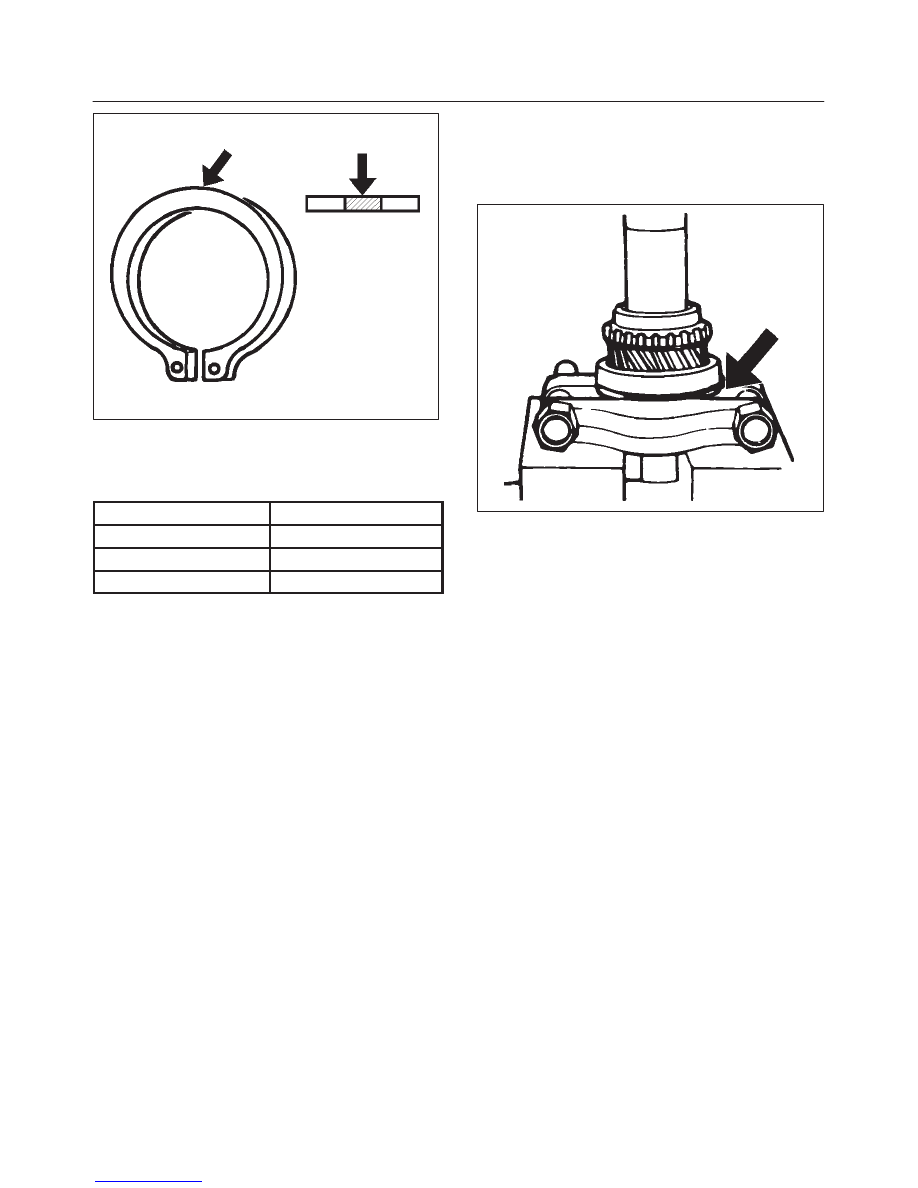
There are three snap ring sizes available.
The snap rings are color coded to indicate their
thickness.
MANUAL TRANSMISSION
7B–63
226RS021
Clutch Hub and Snap Ring Clearance
Standard: 0 – 0.1 mm (0 – 0.004 in)
Snap Ring Availability
Thickness
Color Coding
1.80 mm (0.071 in)
White
1.85 mm (0.073 in)
Yellow
1.90 mm (0.075 in)
Blue
f
Use a pair of snap ring pliers to install the snap ring
to the mainshaft.
The snap ring must be fully inserted into the
mainshaft snap ring groove.
15. Install top block ring(5).
16. Apply grease to the bearing inner and outer
circumferences and install needle bearing(4).
17. Use a bench press to install the top gear shaft ball
bearing(3) to the top gear shaft(2).
226RS059
The snap ring groove must be facing the transmission
front side.
18. Use a pair of snap ring pliers to install the top gear
shaft snap ring(1) to the bearing.
Нет комментариевНе стесняйтесь поделиться с нами вашим ценным мнением.
Текст