Isuzu Rodeo UE. Manual — part 137
6A–37
ENGINE MECHANICAL (X22SE 2.2L)
022RW005
022RW006
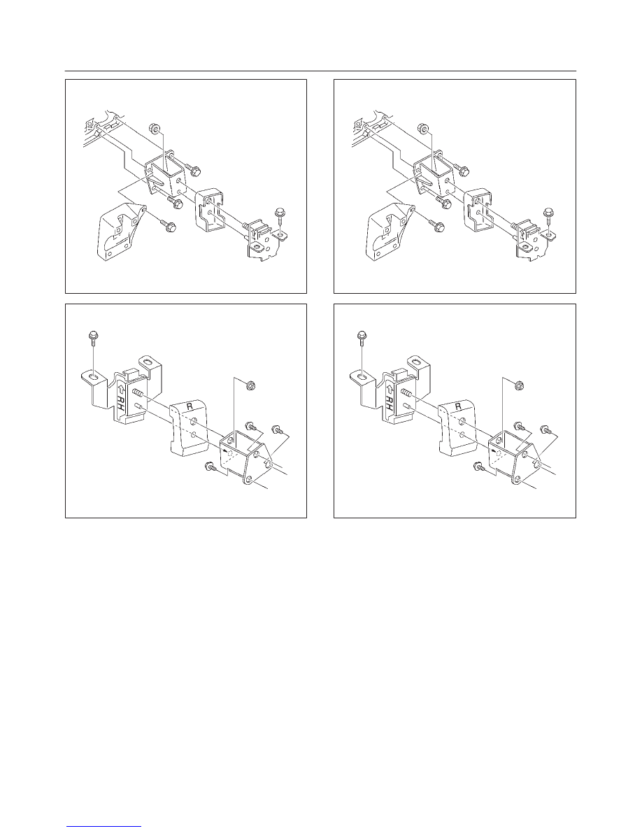
30. Lift up the engine assembly.
Installation
CAUTION: When assembling the engine and
transmission, confirm that dowels have been
mounted in the specified positions at the engine
side. If assembled in the condition that dowels have
not been mounted in the specified position,
transmission damage can result.
1. position the engine assembly in the engine
compartment.
2. Tighten engine mounting bolt to frame side to the
specified torque.
Torque: 41 N·m (30 lb ft)
022RW005
022RW006
3. Install harness clip behind right horn.
4. Install the radiator grille and install flasher lamp
assembly.
5. Install two heater hoses to right side panel.
6. Install radiator lower hose to engine.
7. Install engine ground cable to chassis frame.
8. Connect two chassis harness connectors to right rear
side engine room(under fuse box) and install two
harness clips.
9. Install power steering pump assembly and tighten
fixing bolts.
10. Install transmission assembly, refer to installation
procedure for Transmission section in this manual.
11. Install propeller shaft, refer to installation procedure
for Propeller section in this manual.
12. Connect canister hose next to fuel piping connector.
13. Connect two fuel pipes at right side transmission by
quick type connector.
6A–38
ENGINE MECHANICAL (X22SE 2.2L)
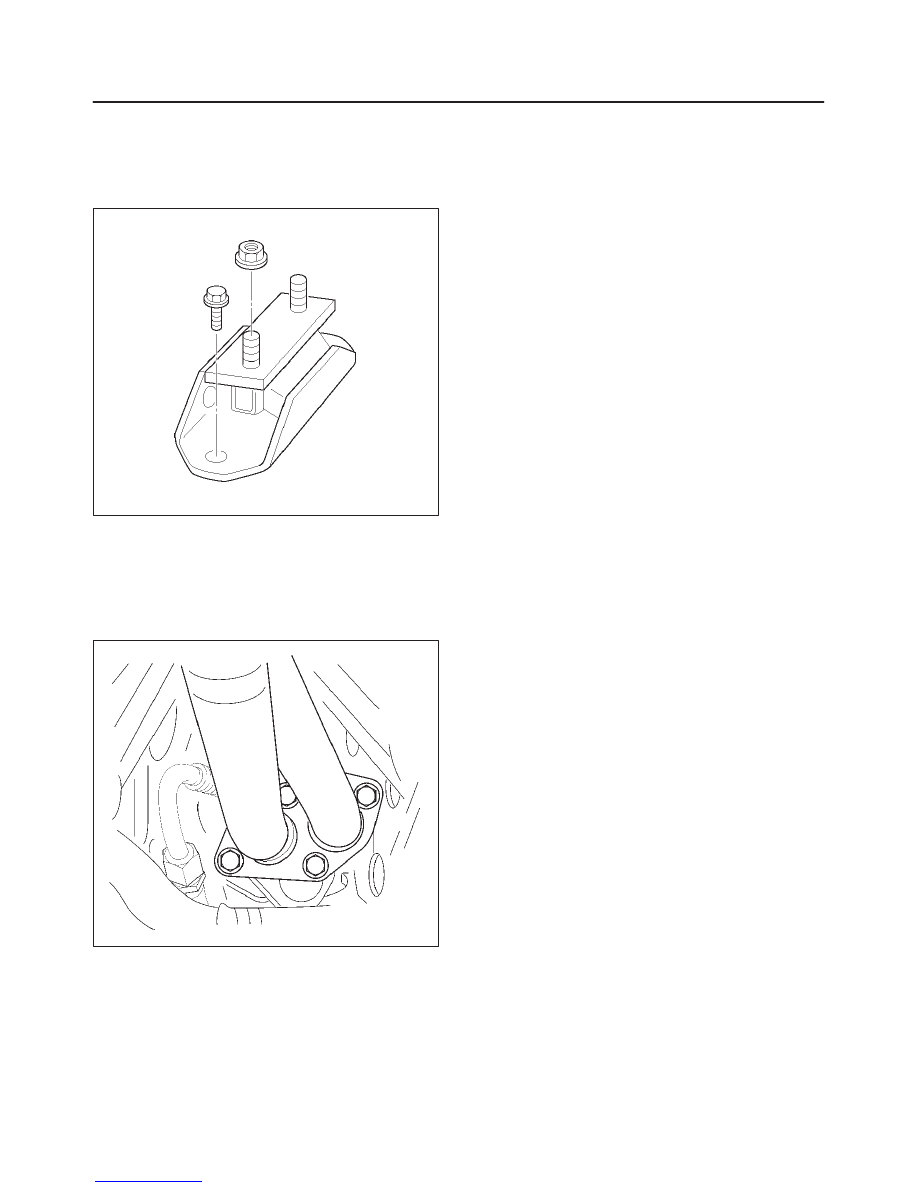
14. Install transmission front under cover to front portion
of clutch housing.
15. Install transmission mounting fixing bolts and nuts to
cross member.
Torque: 50 N·m (36 lb ft)
022RW014
16. Install exhaust front pipe to exhaust manifold and
silencer, then tighten fixing nuts and bolts to the
specified torque.
Torque
25 N·m (18 lb ft) for nut
68 N·m (50 lb ft) for bolt
027RW005
17. Install fuel piping bracket to transmission.
18. Install clutch piping bracket to right side of clutch
housing.
19. Connect ground cable connector to left and right of
front wheel arch upper side.
20. Connect cooling fan harness connector on the left of
fan shroud.
21. Connect vacuum hose to the brake booster.
22. Connect three engine harness connectors to chassis
harness of left rear side of engine compartment.
23. Install air cleaner assembly.
24. Install air duct with air cleaner cover to specified
torque.
Torque
7 N·m (5.1 lb ft) for air duct fixing
3 N·m (2.2 lb ft) for air duct clamp bolt
25. Connect throttle valve control cable to throttle valve
on the intake manifold.
Confirm the free play of throttle valve control cable.
Free play: 5.7 to 6.3 mm
26. Install engine hood to original position.
Refer to installation procedure for Body section in this
manual.
27. Install battery, connect positive cable and ground
cable.
28. Fill engine coolant to full level in the coolant reservoir
tank.

6A–39
ENGINE MECHANICAL (X22SE 2.2L)
Cylinder Head
Cylinder Head and Associated Parts
011RW010
Legend
(1) Cylinder Head Bolt
(2) Camshaft Pulley Fixing Bolt
(3) Camshaft Pulley
(4) Camshaft Oil Seal
(5) Camshaft Bracket Bolt
(6) Camshaft Exhaust
(7) Camshaft Intake
(8) Tappet (HLA)
(9) Split Collar
(10) Valve Spring and Spring Upper Seat
(11) Valve
Disassembly
NOTE:
f
During disassembly, be sure that the valve train
components are kept together and identified so that
they can be reinstalled in their original locations.
f
Before removing the cylinder head from the engine
and before disassembling the valve mechanism,
perform a compression test and note the results.
1. Remove camshaft pulley fixing bolt (2), then pulley
(3).
2. Remove camshaft bracket fixing bolt (5), camshaft
bracket, then camshaft exhaust (6), and intake side
(7).
6A–40
ENGINE MECHANICAL (X22SE 2.2L)
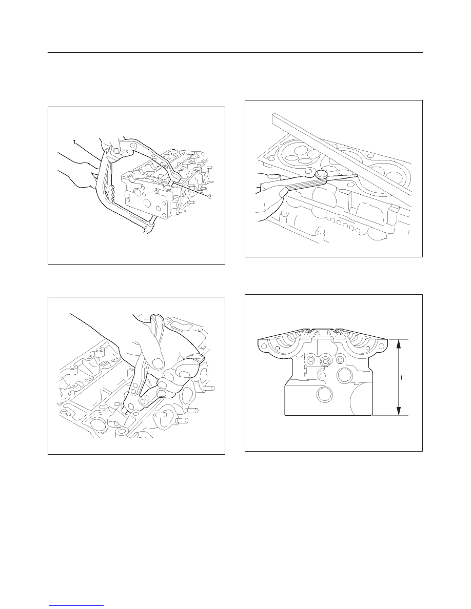
3. Remove cylinder head.
Use J–42623.
4. Valve spring, valve spring caps, compress valve
spring — use J–8062 (1) and Adapter J–42619 (2).
Valve keepers.
011RW014
5. Valves, valve stem seals — use commercially
available remover pliers. Valve spring seats from
cylinder head.
011RW013
Inspection and Repair
1. Check length and width of cylinder head sealing
surfaces for deformation and diagonals for warpage
— use straight edge and feeler gauge.
011RW011
2. Height of cylinder head (sealing surface to sealing
surface).
Dimension (I) – 134 mm
011RW012
Нет комментариевНе стесняйтесь поделиться с нами вашим ценным мнением.
Текст