Isuzu Rodeo UE. Manual — part 138
6A–41
ENGINE MECHANICAL (X22SE 2.2L)
Reassembly
1. Valves, valve stem seals. Refer to Valve Spring, Oil
Controller, Valve, Valve Guide in this section.
2. Valve spring, valve spring caps. Refer to Valve
Spring, Oil Controller, Valve, Valve Guide in this
section.
3. Install tappet (HLA).
4. Cylinder head with new cylinder head bolts to cylinder
block.
Tighten the bolts in 4 steps.
1st step: 25 N·m (18 lb ft)
2nd step: 90
°
3rd step: 90
°
4th step: 90
°
011RW014
5. Camshaft in cylinder head. Refer to Camshaft in this
section.
6. Camshaft pulley. Refer to Camshaft in this section.
6A–42
ENGINE MECHANICAL (X22SE 2.2L)
Valve Spring, Valve, Valve Guide
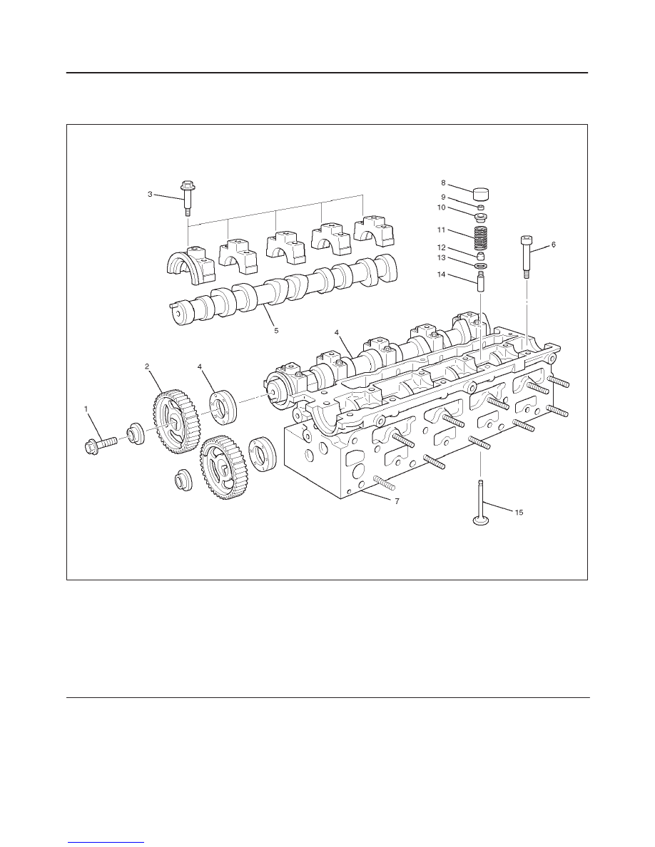
Valve Spring, Valve, Valve Guide and Associated Parts
011RW024
Legend
(1) Camshaft Pulley Fixing Bolts
(2) Camshaft Pulley
(3) Camshaft Bracket Fixing Bolt
(4) Camshaft Assembly Intake
(5) Camshaft Assembly Exhaust
(6) Cylinder Head Bolt
(7) Cylinder Head
(8) Tappet
(9) Split Collar
(10) Spring Upper Seat
(11) Valve Spring
(12) Oil Seal
(13) Spring Lower Seat
(14) Valve Guide
(15) Valve
Disassembly
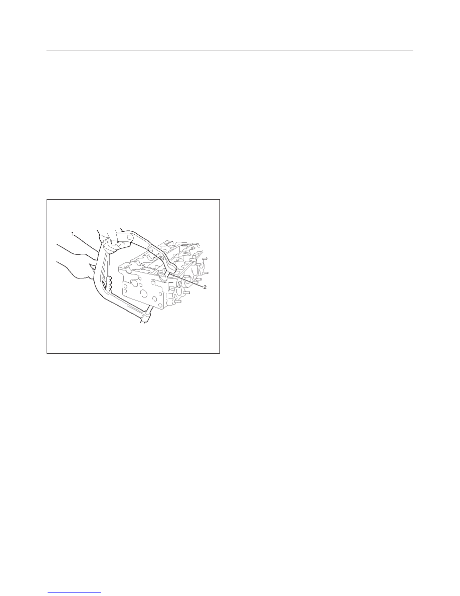
1. Remove camshaft pulley (1), (2).
2. Remove camshaft assembly (Intake) (3), (4).
3. Remove camshaft assembly (Exhaust side) (5).
4. Remove cylinder head (6), (7).
5. Remove tappet (8).
6A–43
ENGINE MECHANICAL (X22SE 2.2L)
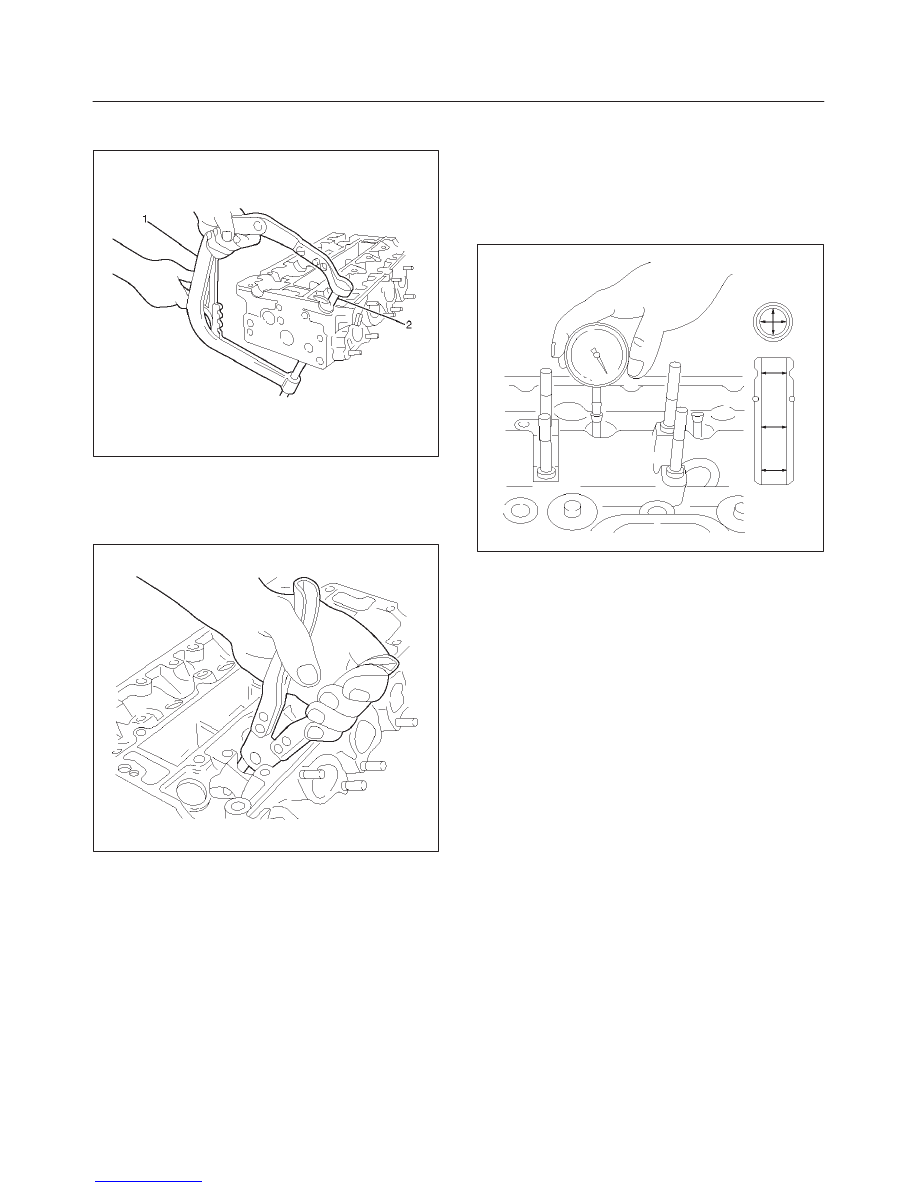
6. Use J–8062 valve spring compressor and J–42619
adapter to remove split collar (9).
011RW014
7. Remove spring upper seat and valve spring (10), (11).
8. Valve, valve guide – use commercially available
remover pliers.
Valve spring lower seat from cylinder head.
011RW013
Inspection and Repair
1. Use a internal micrometer to measure the diameter
valve guide.
Valve stem play
Intake : 0.03 to 0.057 mm (0.0012 to 0.0022 in)
Exhaust : 0.04 to 0.067 mm (0.0016 to 0.0026 in)
011RW020
Valve Guide
CAUTION: Taking care not to damage the valve seat
contact surface, when removing carbon adhering to
the valve head. Carefully inspect the valve stem for
scratching or abnormal wear. If these conditions are
present, the valve and the valve guide must be
replaced as a set.
Valve Seat
Valve seat width in cylinder head
Intake: 1.0 to 1.5 mm (0.039 to 0.0585 in)
Exhaust: 1.7 to 2.2 mm (0.0663 to 0.0858 in)
Valve Seat Insert Correction
Remove the carbon from the valve seat insert surface.

6A–44
ENGINE MECHANICAL (X22SE 2.2L)
Valve Seat Insert Replacement
1. Arc weld the rod at several points. Be careful not to
damage the aluminum section.
2. Allow the rod to cool for a few minutes. This will cause
the valve seat to shrink.
3. Strike the rod and pull it out.
014RS015
4. Carefully clean the valve seat press–fit section on the
cylinder head side.
5. Heat the press–fit section with steam or some other
means to cause expansion. Cool the valve seat with
dry ice or some other means.
6. Insert the press–fit section into the valve seat
horizontally.
7. Lap the valve and the seat.
Reassembly
1. Install oil controller (3) and spring lower seat (2).
Using oil controller replacer J–42622, drive in a new
oil controller.
014RS019
2. Install valve to valve guide. Before install valve guide
apply engine oil to the outside of the valve stem.
3. Install valve spring to cylinder head. Attach the valve
spring to the lower spring seat.
4. Install lower valve spring seat, valve spring and upper
valve spring seat then put split collars on the upper
spring seat, using J–8062 valve spring compressor
for install the split collars.
011RW014
5. Install tappet.
6. Install camshaft assembly.
f
Refer to installation procedure for Camshaft in this
manual.
Нет комментариевНе стесняйтесь поделиться с нами вашим ценным мнением.
Текст