Isuzu Rodeo UE. Manual — part 76
4C–13
DRIVE SHAFT SYSTEM
Front Drive Shaft Joint
Front Drive Shaft Joints Replace-
ment
f
Refer to Front Drive Axle Assembly Replacement in
this section, and refer to Front Hub and Disc Overhaul
in Suspension section.
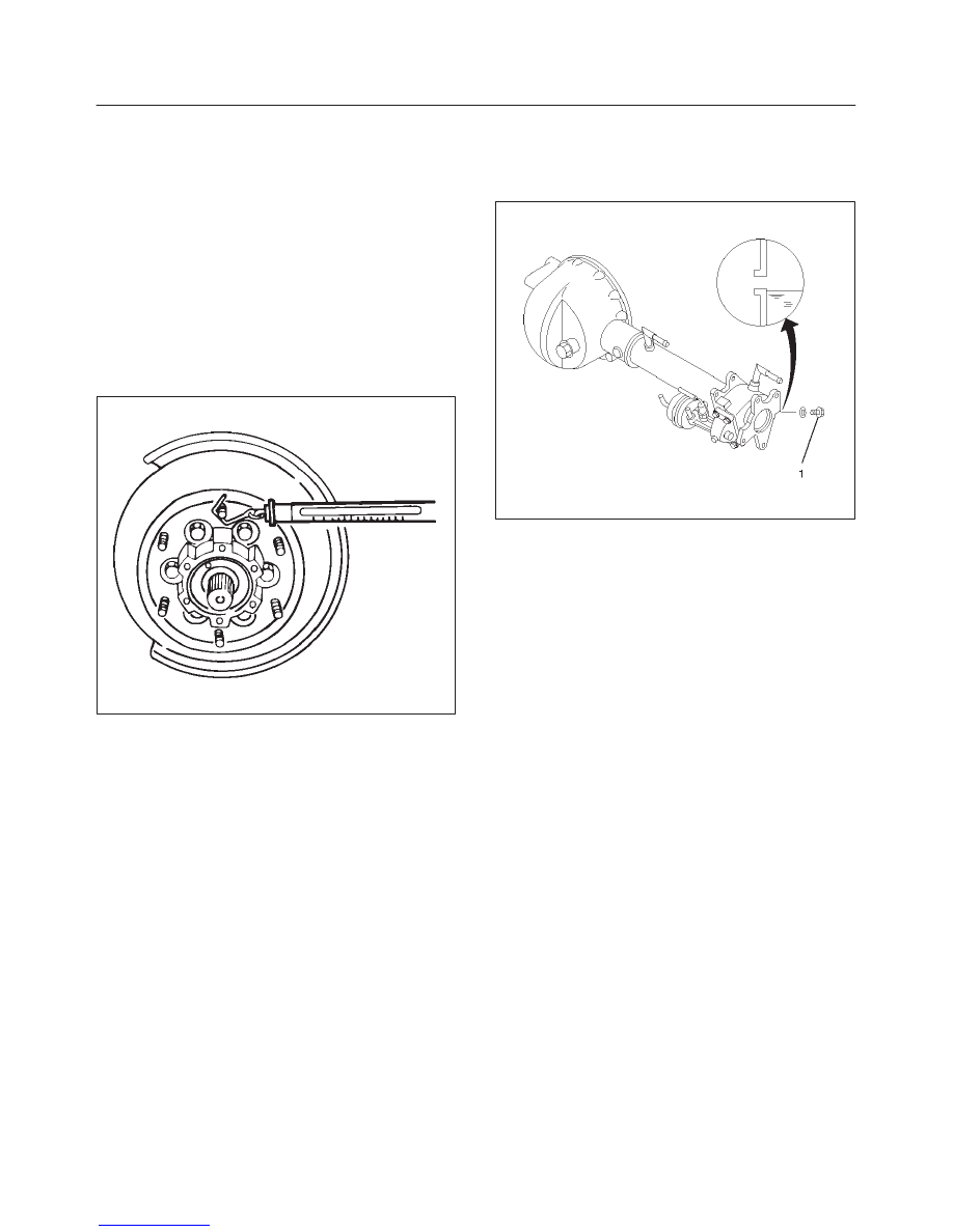
Front Hub Bearing Preload Check
Check the hub bearing preload at the wheel pin.
New bearing and New oil seal:
19.6 – 24.5 N (4.4 – 5.5 lb)
Used bearing and New oil seal:
11.8– 17.7 N(2.6 – 4.0 lb)
411RS011
Inspection Of Shift On The Fly System
Gear Oil
412RW035
1. Open filler plug and make sure that the oil up to the
plug port.
If the oil is short, replenish with gear oil GL–5 grade.
2. Tighten the filler plug to specified torque.
Torque: 78 N·m (58 lb in)
4C–14
DRIVE SHAFT SYSTEM
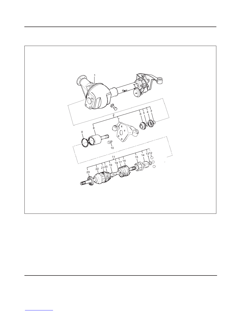
Front Axle Drive Shaft
Front Axle Drive Shaft and Associated Parts
412RW033
Legend
(1) Axle Case and Differential
(2) DOJ Case Assembly
(3) Snap Ring
(4) Bearing
(5) Snap Ring
(6) Oil Seal
(7) Bracket
(8) DOJ Case
(9) Circlip
(10) Bolt
(11) Drive Shaft Joint Assembly
(12) Ball
(13) Snap Ring
(14) Ball Retainer
(15) Ball Guide
(16) Band
(17) Bellows
(18) Band
(19) Band
(20) Bellows
(21) Band
(22) BJ Shaft
(23) Dust Seal
4C–15
DRIVE SHAFT SYSTEM
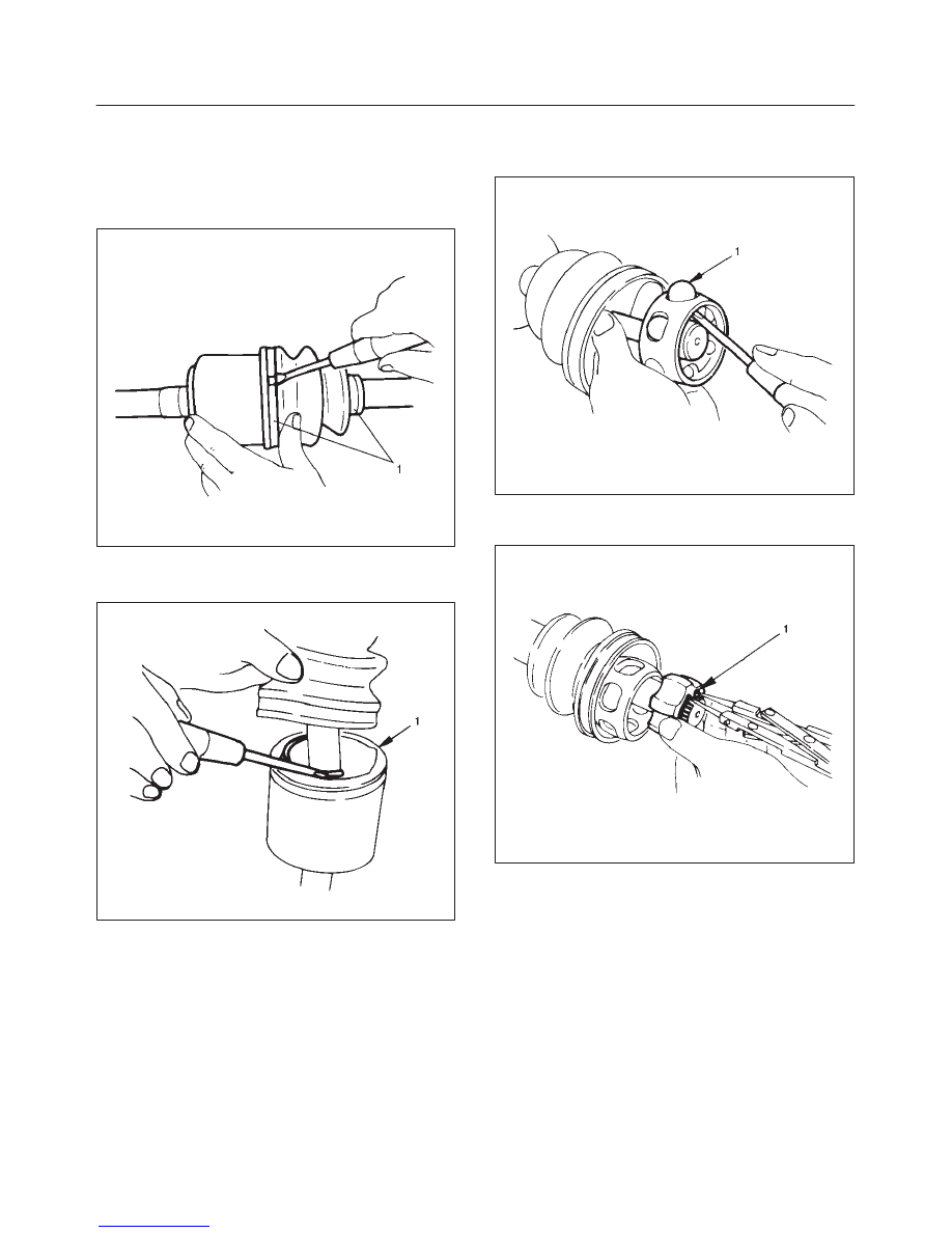
Disassembly
NOTE: For the left side, follow the same steps as right
side.
1. Raise the hooked end of the band with a screwdriver
or equivalent.
412RS009
2. Remove band(1).
3. Pry off circlip (1) with a screwdriver or equivalent.
412RS010
4. Remove drive shaft joint assembly.
5. Remove the six balls (1) with a screwdriver or
equivalent.
412RS012
6. Using snap ring pliers, remove the snap ring (1)
fastening the ball retainer to the center shaft.
412RS013
4C–16
DRIVE SHAFT SYSTEM
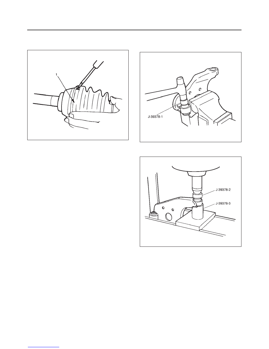
7. Remove ball retainer, ball guide and bellows.
8. Raise the hooked end of the band with a screwdriver
or equivalent.
412RS014
9. Remove band(1).
10. Remove bellows.
11. Remove dust seal.
12. Remove BJ shaft assembly.
13. Remove the mounting bracket fixing bolts, and then
remove DOJ case assembly from the axle case.
14. Remove snap ring and bearing.
15. Remove snap ring and oil seal.
16. Remove bracket.
Inspection And Repair
Make necessary correction or parts replacement if wear,
damage, corrosion or any other abnormal condition are
found through inspection.
Check the following parts.
1. Drive shaft joint assembly
2. DOJ case, ball, ball guide, ball retainer
3. Bellows
4. Bearing
5. Dust seal, oil seal
Bushing Replacement
f
Remove the bushings using a remover J–39378–1
and hammer.
412RS015
f
By using installer J–39378–2 and base J–39378–3,
press fit the bushings into the bracket.
412RS016
Reassembly
1. Install DOJ case to bracket.
2. Install oil seal and fix snap ring.
3. Install bearing and fix snap ring.
4. Install bracket to axle case. Tighten the bracket bolt to
the specified torque.
Torque: 116 N·m (85 lb ft)
5. Apply 150g of the specified grease in BJ.
6. Install dust seal.
7. Apply a thin coat of grease to the shaft for smooth
installation then install bellows.
Нет комментариевНе стесняйтесь поделиться с нами вашим ценным мнением.
Текст