Isuzu Rodeo UE. Manual — part 75
4C–9
DRIVE SHAFT SYSTEM
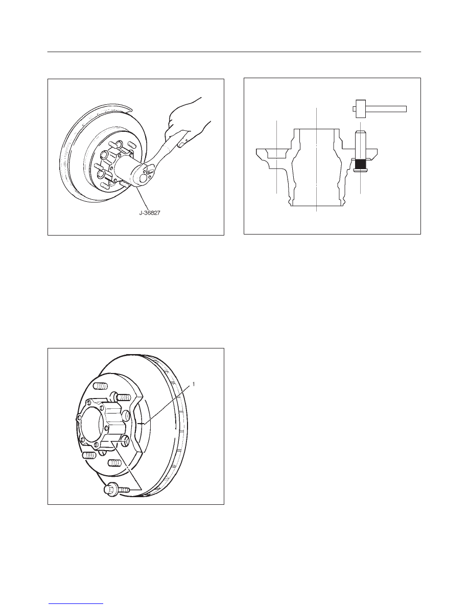
8. Remove lock washer and lock screw.
9. Use wrench J–36827, remove hub nut.
901RW054
10. Remove hub and disc assembly.
11. Remove ABS sensor ring.
12. Remove outer bearing.
13. Remove oil seal.
14. Remove inner bearing.
15. Remove bolt , if necessary, replace the wheel pin in
the following manner.
f
Apply a scribe mark(1) to disc to hub.
f
Clamp the hub and disc assembly in a vise, using
protective pads. Remove the 6 disc–to–hub
retaining bolts.
411RS003
f
Place hub on a suitable work surface and remove
the studs by using a hammer.
411RS004
Inspection and Repair
Make necessary correction or parts replacement if wear,
damage, corrosion or any other abnormal condition are
found through inspection.
Check the following parts.
f
Hub
f
Hub bearing oil seal
f
Knuckle spindle
f
Disc
f
Caliper
f
Shift on the fly system parts (Cap, Hub flange, Shim,
Snap ring)
f
ABS sensor ring
For inspection and servicing of disc caliper and related
parts, refer to Disc Brakes in Brake section.
4C–10
DRIVE SHAFT SYSTEM
Reassembly
1. Install wheel pin.
f
Place the hub on a wood workbench or a block of
wood approx. 6” by 6” to protect the wheel stud
ends and threads.
f
Insert a wheel stud using a hammer.
Be sure the wheel stud is started squarely and
seats completely.
411RS005
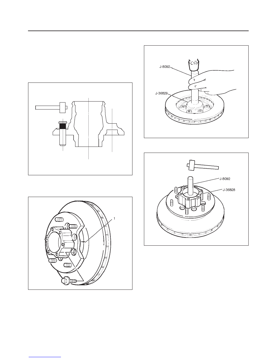
2. Align scribe marks(1) and attach the hub to the disc,
then tighten the bolts to the specified torque.
Torque: 103 N·m (76 lb ft)
411RS003
3. Use installer J–36829 and grip J–8092, then install
the inner bearing by driving it into the hub.
901RW055
4. Use installer J–36828 and grip J–8092 then install the
outer bearing by driving it into the hub.
901RW056
4C–11
DRIVE SHAFT SYSTEM
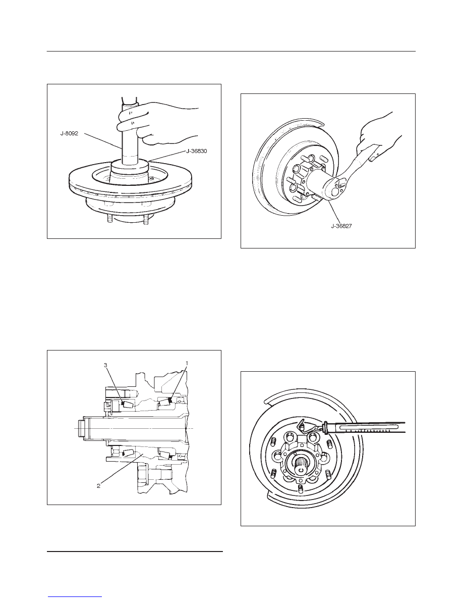
5. Apply grease (NLGI No.2 or equivalent) to the lip
portion, then install oil seal by using installer J–36830
and grip J–8092.
901RW057
6. Install ABS sensor ring, then tighten the bolts to the
specified torque.
Torque: 18 N·m (13 lb ft)
7. Install hub and disc assembly.
f
Apply grease in the hub.
f
Apply wheel bearing type grease NLGI No. 2 or
equivalent to the outer and inner bearing.
Grease Amount
f
Hub: 35 g (1.23 oz)
f
Outer bearing: 10 g (0.35 oz)
f
Inner bearing: 15 g (0.53 oz)
411RS009
Legend
(1) Inner Bearing
(2) Hub
(3) Outer Bearing
8. Install hub nut.
Turn to the place where there is a chamfer in the
tapped hole to the outer side, then attach the nut by
using front hub nut wrench J–36827.
901RW054
Preload Adjustment
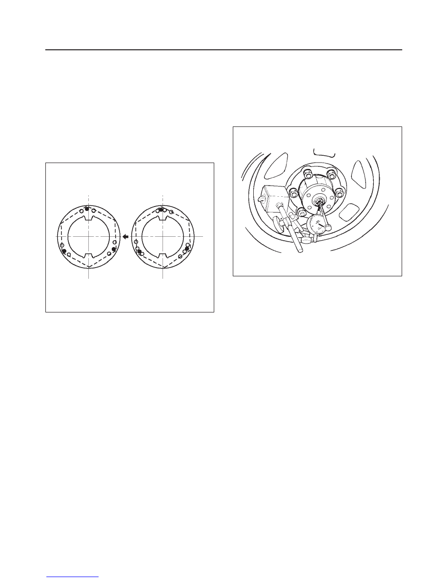
1. Tighten the hub nut to 29 N·m (22 lb ft), then fully
loosen the nut.
2. Tighten the hub nut to the value given below,
using a spring scale on the wheel pin.
New bearing and New oil seal
Bearing Preload: 20 N – 25 N (4.4 lb – 5.5 lb)
Used bearing and New oil seal
Bearing Preload: 12 N – 18 N (2.6 lb – 4.0 lb)
If the measured bearing preload is outside the
specifications, adjust it by loosening or tightening the
bearing nut.
411RS011
4C–12
DRIVE SHAFT SYSTEM
9. Install lock washer and lock screw in the following
manner.
f
Turn the side with larger diameter of the tapered
bore to the vehicle outer side, then attach the
washer.
f
If the bolt holes in the lock plate are not aligned with
the corresponding holes in the nut, reverse the lock
plate.
f
If the bolt holes are still out of alignment, turn in the
nut just enough to obtain alignment.
f
Screw is to be fastened tightly so its head may
come lower than the surface of the washer.
411RS012
10. Apply adhesive (LOCTITE 515 or equivalent) to both
joining flange faces then install hub flange.
11. Install snap ring and shim.
f
Adjust the clearance between the free wheeling hub
body and the snap ring.
Clearance: 0 mm–0.3 mm (0 in–0.012 in)
Shims Available: 0.2 mm, 0.3 mm, 0.5 mm,
1.0 mm (0.008 in, 0.012 in, 0.020 in, 0.039 in)
411RW002
12. Install hub cap.
13. Tighten the bolts to the specified torque.
Torque: 59 N·m (43 lb ft)
Нет комментариевНе стесняйтесь поделиться с нами вашим ценным мнением.
Текст