Isuzu Rodeo UE. Manual — part 74

4C–5
DRIVE SHAFT SYSTEM
Reassembly
1. Install wheel pin.
f
Place hub on a wood workbench or a block of wood
approx. 6” by 6” to protect the wheel stud ends and
threads.
f
Install wheel stud, using a hammer.
NOTE: Be sure wheel stud is started squarely and seats
completely.
411RS005
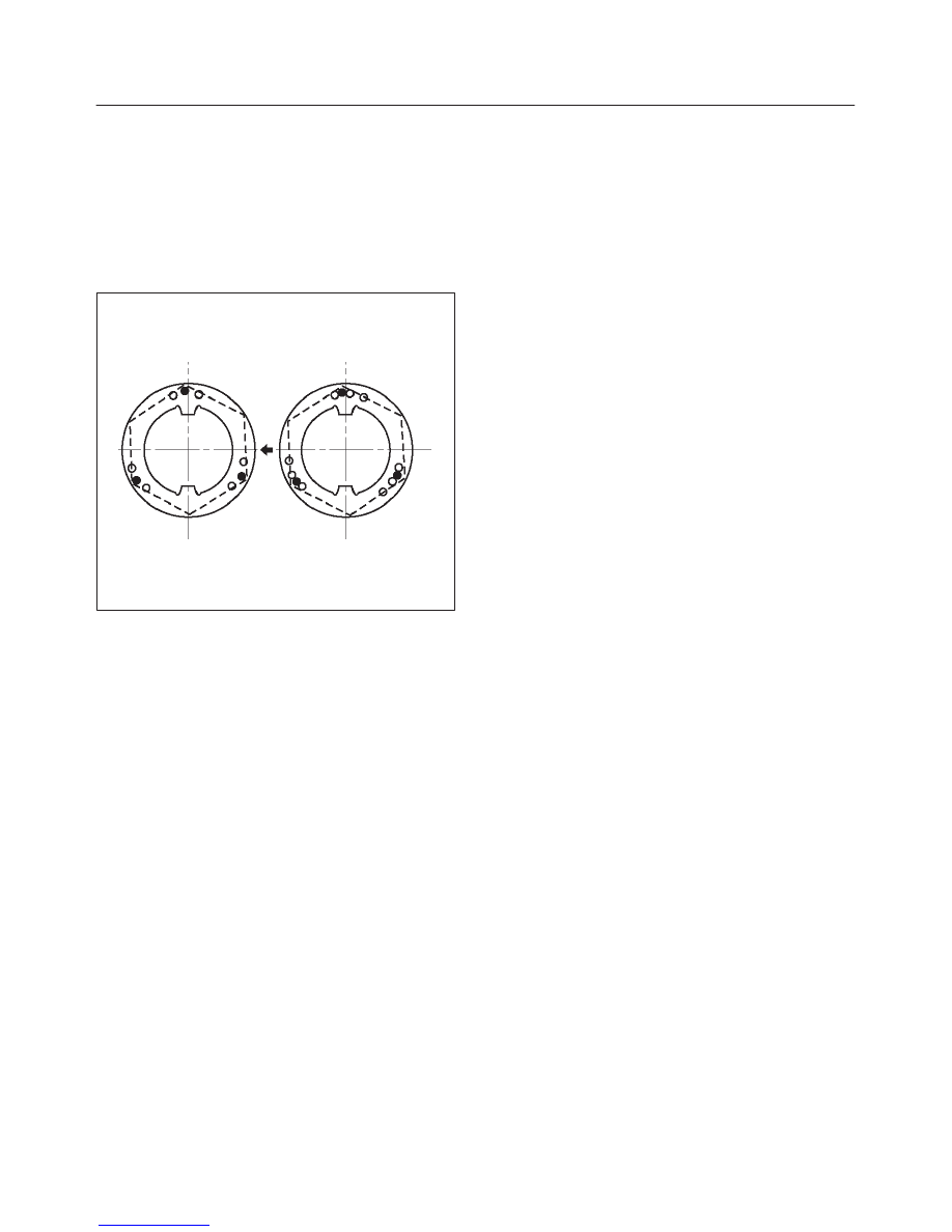
2. Align index marks(1) and install hub to disc.
411RS003
3. Install bolt.
Tighten the bolts to the specified torque.
Torque: 103 N·m (76 lb ft)
411RS021
4. Install outer bearing.
Install the outer race by driving it into the hub by using
installer J–36828 and grip J-8092.
901RW056
4C–6
DRIVE SHAFT SYSTEM
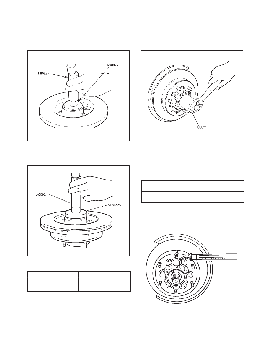
5. Install inner bearing.
Install the outer race by driving it into the hub by using
installer J–36829 and grip J–8092.
411RS023
6. Install oil seal by using installer J–36830 and grip
J–8092.
Apply Multipurpose grease NLGI No. 2 or equivalent
to the lip portion.
901RW057
7. Apply Multipurpose grease NLGI No.2 in the hub and
bearing.
Hub
35 g (1.23 oz)
Outer bearing
10 g (0.35 oz)
Inner bearing
15 g (0.53 oz)
8. Install hub nut by using wrench J–36827.
Turn the place where there is a chamfer in the tapped
hole to the outer side, and attach the nut.
901RW054
Preload Adjustment
1. Tighten the hub nut to 29.4 N·m (21.7 lb ft), then
loosen the nut to the full.
2. Tighten the hub nut to the value given below,
using a spring scale on the wheel pin.
Bearing Preload
New bearing and New
oil seal
19.6 – 24.5 N
(4.4 – 5.5 lb)
Used bearing and New
oil seal
11.8 – 17.7 N
(2.6 – 4.0 lb)
If the measured bearing preload is outside the
specifications, adjust it by loosening or tightening
the bearing nut.
411RS011
4C–7
DRIVE SHAFT SYSTEM
9. Install lock washer.
f
Turn the side with larger diameter of the tapered
bore to the vehicle outer side, then attach the
washer.
If the bolt holes in the lock plate are not aligned with
the corresponding holes in the nut, reverse the lock
plate. If the bolt holes are still out of alignment, turn
in the nut just enough to obtain alignment. Screw is
to be fastened tightly so its head may come lower
than the surface of the washer.
411RS012
10. Install cover and tighten the cover bolt.
11. Install brake caliper and tighten fixing bolt.
4C–8
DRIVE SHAFT SYSTEM
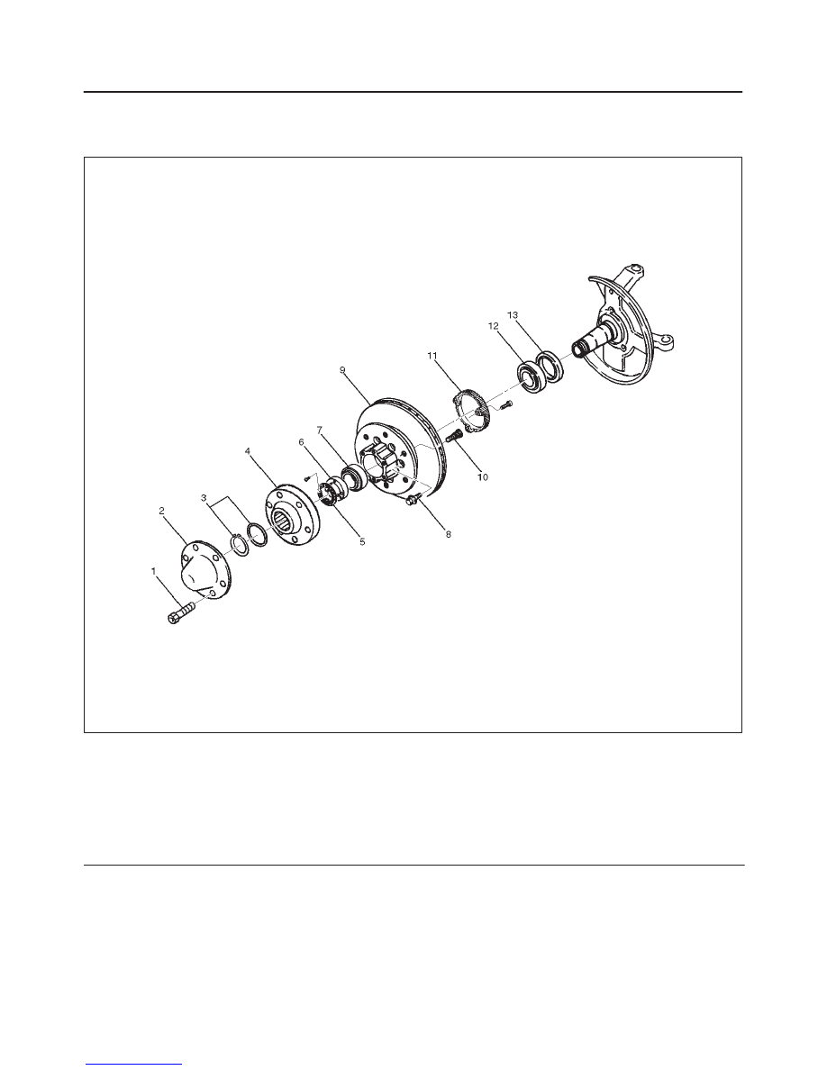
Front Hub and Disc (4WD Model)
Disassembled View
411RW001
Legend
(1) Bolt
(2) Cap
(3) Snap Ring and Shim
(4) Hub Flange
(5) Lock Washer and Lock Screw
(6) Hub Nut
(7) Outer Bearing
(8) Bolt
(9) Hub and Disc Assembly
(10) Wheel Pin
(11) ABS Sensor Ring
(12) Inner Bearing
(13) Oil Seal
Disassembly
1. Before disassembly, select the 2WD position with the
4WD switch.
2. Jack up the front of vehicle and support frame with
jack stands.
3. Remove the disc brake caliper assembly and hang it
on the frame with wires. Refer to Disk Brakes in Brake
section.
4. Remove Bolt.
5. Remove cap.
6. Remove snap ring and shim.
7. Remove hub flange.
Нет комментариевНе стесняйтесь поделиться с нами вашим ценным мнением.
Текст