Isuzu Rodeo UE. Manual — part 516
7B–96
MANUAL TRANSMISSION
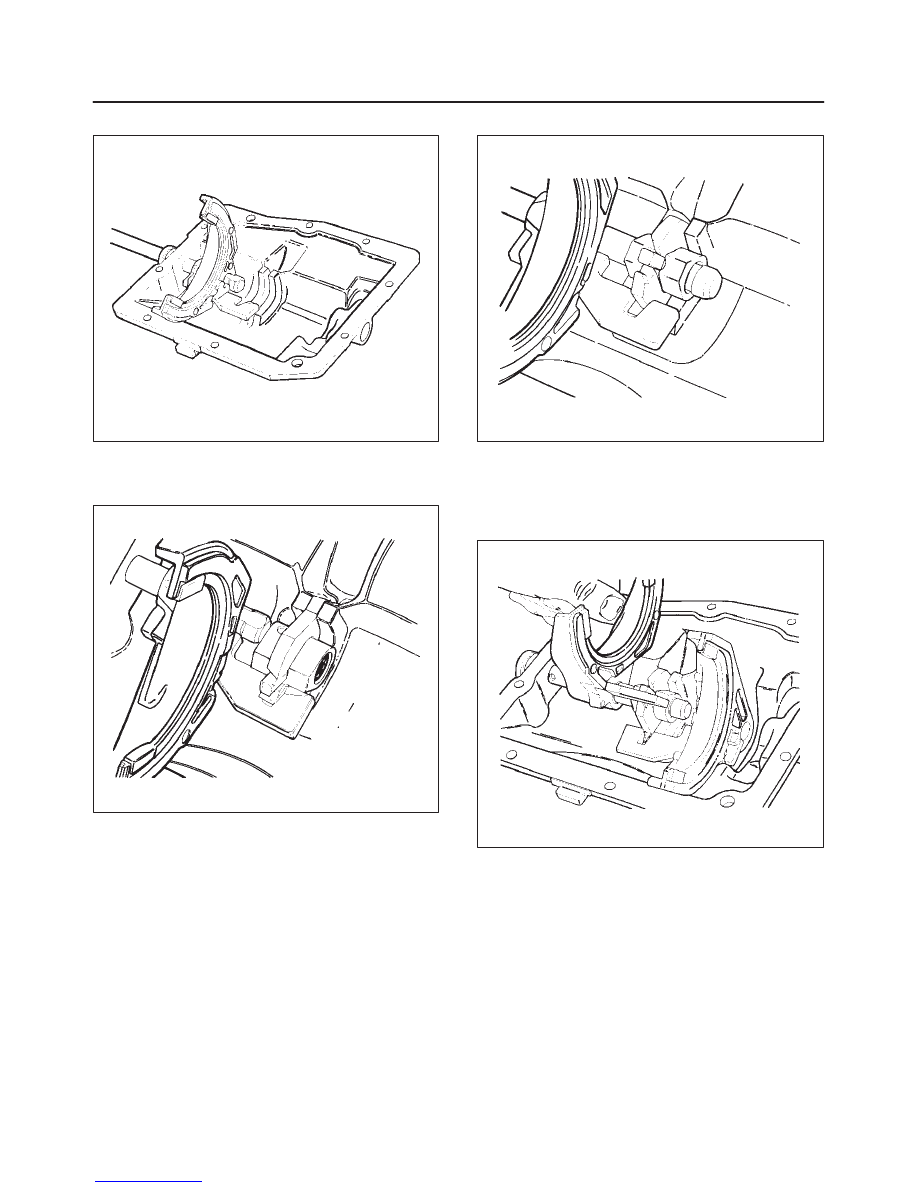
5. Push the shift shaft through the 1–2 shift fork.
230RS032
6. Place the selector arm(5) and interlock plate(6) in the
cover(10). Note the position of the interlock plate(6)
and selector arm(5).
230RS033
7. Push the shift shaft through the selector arm(5).
230RS034
8. Install the fork pads(3) and selector plate(4) onto the
3–4 shift fork(3).
9. Place the 3–4 shift fork(3) in the cover(10) with its
selector plate(4) facing the rear of the cover. Note the
position of the 3–4 and 1–2 selector plates(4).
230RS035

MANUAL TRANSMISSION
7B–97
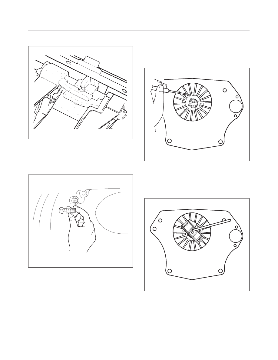
10. Push the shift shaft(2) through the 3–4 shift fork(3)
and into the front of the cover(10).
230RS036
11. Install the roll pin(1) that holds the selector arm(5) to
the shift shaft(2).
230RS038
12. Lubricate and install the O-ring(9) on the rear of the
shift cover(10).
230RS038
Check the shift cover parts for proper assembly
by doing the following:
f
Insert a 3/16–inch diameter pin punch into the offset
lever hole of the shift shaft(2).
f
Hold the shift cover(10) parallel to the floor and
rotate the shift shaft(2) so that the punch is vertical.
230RS039
7B–98
MANUAL TRANSMISSION
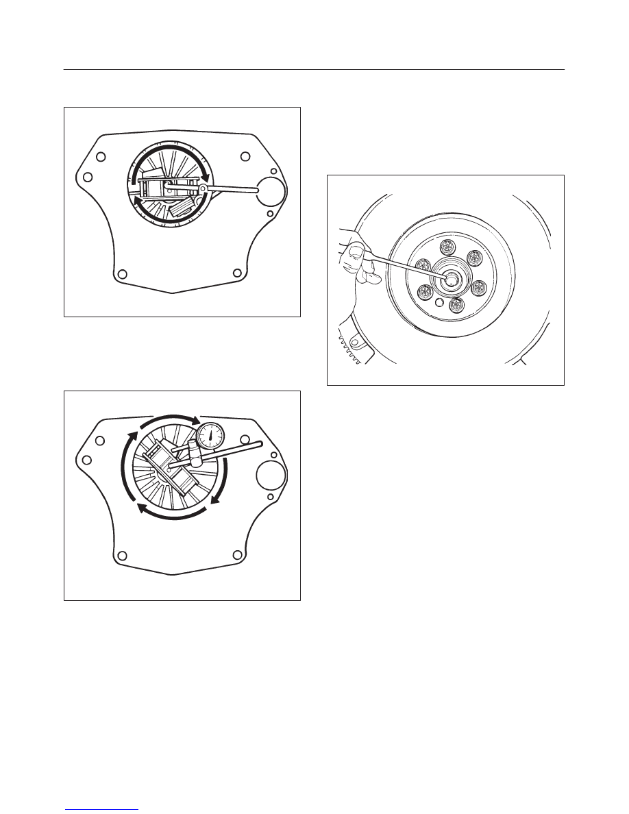
f
Look at the selector arm: it should be aligned with
the 3–4 shift fork select plate.
220RT012
Pre-Installation Checks (TREMEC
T5R)
1. Separate the clutch release fork from its ball stud and
remove the ball stud from the clutch housing.
220RW060
2. Inspect these parts:
f
Ball stud
f
Fork
f
Release bearing
f
Fingers of the pressure plate spring.
201RS030
Replace any parts which have excessive wear.
3. Check the alignment of the clutch housing to the
engine in these steps:
f
Place the magnetic base for a dial indicator on the
pressure plate spring fingers.
Make sure the base is secure.
201RS031
MANUAL TRANSMISSION
7B–99
f
Check the housing bore alignment by:
– Mounting the dial indicator against the bore
201RS032
– Rotating the engine one revolution while recording
total dial indicator needle travel
f
Check the housing face alignment by:
– Mounting the dial indicator against the housing
face
201RS033
– Rotating the engine one revolution while recording
total dial indicator needle travel
If either reading is greater than 0.254 mm
(0.010 inch), place special shims between the engine
and clutch housing to correct the misalignment.
4. Check the condition of these clutch system parts if
you suspect excessive wear:
f
Pressure plate assembly
f
Driven disc (especially the torsional damping
springs)
f
Flywheel
f
Input shaft pilot bearing.
015RS076
Replace any parts which have excessive wear.
5. Reassemble the clutch system parts. Be sure to
lubricate the clutch release bearing bore and fork
groove and also the head of the fork pivot.
Нет комментариевНе стесняйтесь поделиться с нами вашим ценным мнением.
Текст