Isuzu Rodeo UE. Manual — part 9
1A–6
HEATING, VENTILATION AND AIR CONDITIONING (HVAC)
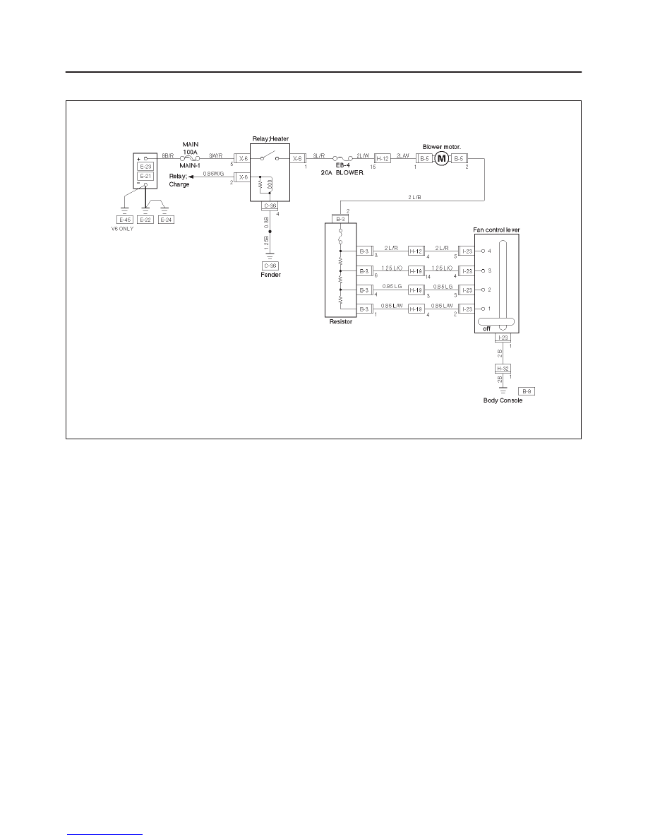
Wiring Diagram
D08RW060

HEATING, VENTILATION AND AIR CONDITIONING (HVAC)
1A–7
Diagnosis
Heating Cycle diagnosis
Condition
Possible cause
Correction
No heating or insufficient heating.
Blower motor does not run or runs
improperly.
Refer to “FAN CONTROL LEVER
(FAN SWITCH) DIAGNOSIS”.
Engine coolant temperature is low.
Check the engine coolant
temperature after warming up the
engine and check the thermostat.
Replace as necessary.
Insufficient engine coolant.
Add engine coolant as required.
Circulation volume of engine coolant
is insufficient.
Check if the water hose to the heater
core is clogged, collapsed or twisted.
Repair or replace as necessary.
Heater core clogged or collapsed.
Clean or replace as necessary.
The heater cores is not provided with
air sent from the blower motor.
Repair the temperature control link
unit or mode doors.
Duct connections defective or
unsealing.
Repair or replace as necessary.
Control lever moves but mode door
does not operate
Cable attaching clip is not correct.
Repair
does not operate.
Link unit of heater or blower
assembly defective.
Repair
The mode door cannot be set to the
mode selected.
Link unit of heater unit or blower
assembly defective.
Repair.
Control cable is not adjusted.
Adjust.
1A–8
HEATING, VENTILATION AND AIR CONDITIONING (HVAC)
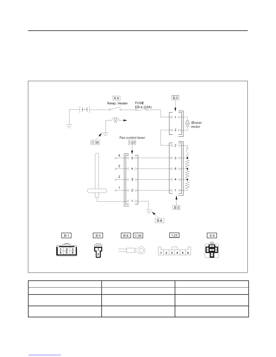
Fan Control Lever (Fan Switch) Diagnosis
Current flows to the blower motor through the heater relay
(X-6) to activate the rotation of the blower motor by
turning “ON” the fan control knob (fan switch). Blower
motor speed is controlled in stages by the resistor, by
operating the switch from “LOW” to “HIGH”.
For the inspection of the relays, switches and units in
each table, refer to “INDIVIDUAL INSPECTION” in this
section.
D08RW059
Condition
Possible cause
Correction
Blower motor does not run.
—
Refer to Chart A
Blower motor does not run in certain
position (s).
—
Refer to Chart B, C, D and E
Blower motor does not stop at “OFF”
position.
—
Refer to Chart F
HEATING, VENTILATION AND AIR CONDITIONING (HVAC)
1A–9
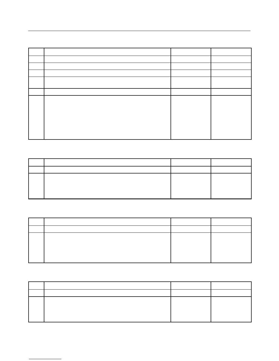
Chart “A” Blower Motor Does Not Run
Step
Action
Yes
No
1
Is relay (X-6) OK?
Go to Step 2
Replace
2
Is fuse EB-4 (20A) OK?
Go to Step 3
Replace
3
Is resistor OK?
Go to Step 4
Replace
4
Is fan control lever OK?
Go to Step 5
Replace control
lever assembly.
5
Is blower motor OK?
Go to Step 6
Replace
6
1. Turn the ignition switch “ON”.
2. Turn fan control lever “ON”.
3. Check to see if battery voltage is present at chassis side
connector terminal No. B5-1
Is there a battery voltage?
Poor ground or
open circuit either
between chassis
side connector
terminal No. B5-2
and No. B3-2 or
No. I23-1 and
body ground (No.
B-8).
Open circuit
between No.
EB-4 (20A) fuse
and No. B5-1.
Chart “B” Blower Motor Does Not Run At Low Position
Step
Action
Yes
No
1
Is resistor OK?
Go to Step 2
Replace
2
Is fan control lever (Fan Switch) OK?
Open circuit
between chassis
side connector
terminal No. B3-1
and No.I23-2.
Replace control
lever assembly.
Chart “C” Blower Motor Does Not Run At Medium Low Position
Step
Action
Yes
No
1
Is resistor OK?
Go to Step 2
Replace
2
Is fan control lever (Fan Switch) OK?
Open circuit
between the
chassis side
connector
terminal No. B3-4
and No. I23-3.
Replace control
lever assembly.
Chart “D” Blower Motor Does Not Run At Medium High Position
Step
Action
Yes
No
1
Is resistor OK?
Go to Step 2
Replace
2
Is fan control lever (Fan Switch) OK?
Open circuit
between chassis
side connector
terminal No. B3-6
and No. I23-4.
Replace control
lever assembly.
Нет комментариевНе стесняйтесь поделиться с нами вашим ценным мнением.
Текст