Isuzu Rodeo UE. Manual — part 105
5A–43
BRAKE CONTROL SYSTEM
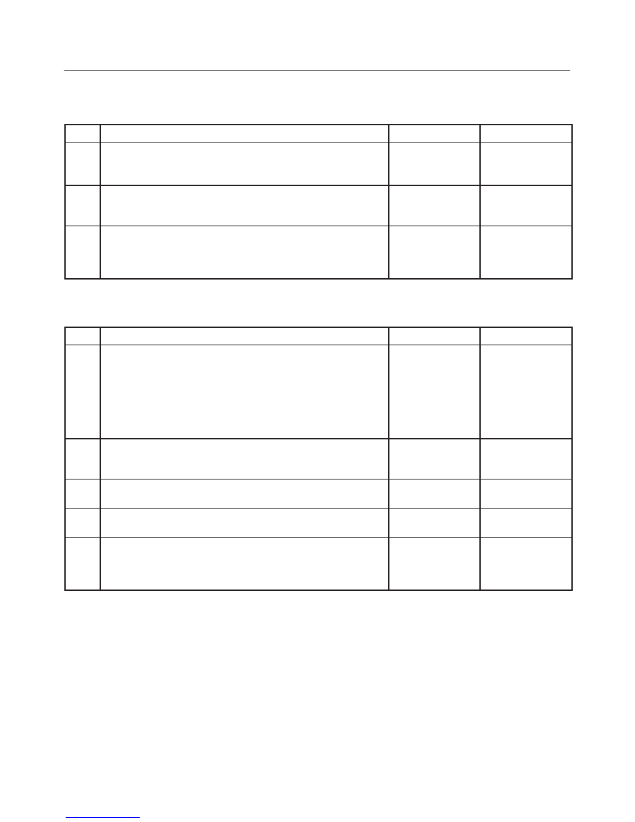
Chart B-8 2WD Controller in 4WD Vehicle Controller (DTC 13 (Flash out) / C0285 (Serial
communications)), 4WD State Input Signal Failure (DTC 24 (Flash out) / C0282 (Serial
communications))
Step
Action
Yes
No
1
Remove coil integrated module connector.
Is the coil integrated module connector (C-4) terminal 8 line
normally?
Go to Step 2
Repair.
Go to Step 3
2
Is the 4WD controller normally?
Replace EHCU.
Go to Step 3
Replace 4WD
controller.
Go to Step 3
3
1. Reconnect all components, ensure all components are
properly mounted.
2. Clear diagnostic trouble code.
Was this step finished?
Repeat the “Basic
diagnostic flow
chart”
Go to Step 3
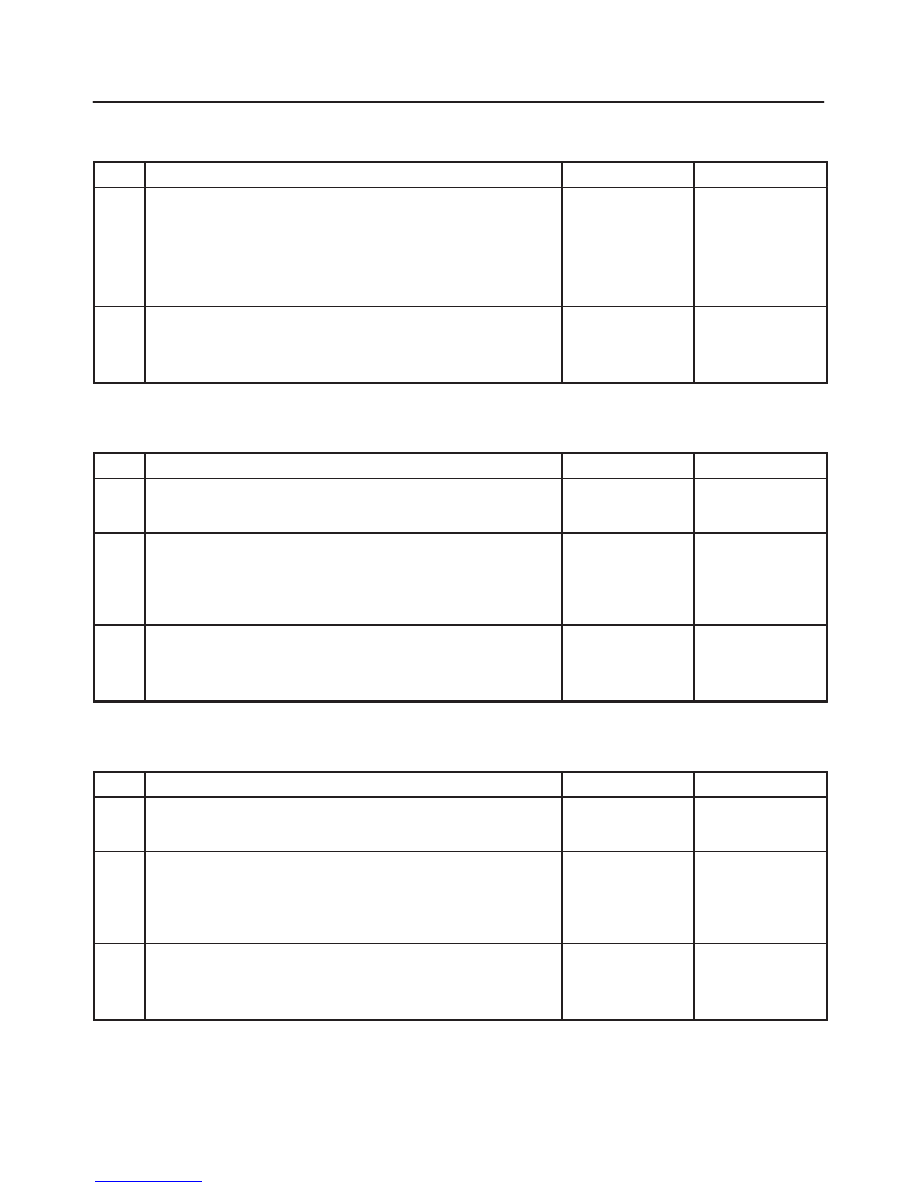
Chart B-9 Pump Motor Failure (DTC 32 (Flash out) / C0267, C0268 (Serial
communications))
Step
Action
Yes
No
1
1. Turn the key off.
2. Disconnect coil integrated module connector.
3. Measure the voltage between terminal 1 of the coil integrated
module connector (C-5) and body ground.
Is the voltage equal to the battery voltage?
Go to Step 2
Repair
fuse/harness
between battery
and coil
integrated
module connector
(C-5) terminal 1.
Go to Step 5
2
Is the harness from the hydraulic unit connected to the coil
integrated module connector?
Go to Step 3
Connect to the
connector.
Go to Step 3
3
Is the harness from the hydraulic unit normally?
Go to Step 4
Replace EHCU.
Go to Step 5
4
Is the check resistance of hydraulic unit connector terminals 1 and
2 between 0.2 and 1.0 ohms?
Replace EHCU.
Go to Step 5
Replace EHCU.
Go to Step 5
5
1. Reconnect all components, ensure all components are
properly mounted.
2. Clear diagnostic trouble code.
Was this step finished?
Repeat the “Basic
diagnostic flow
chart”
Go to Step 5
5A–44
BRAKE CONTROL SYSTEM
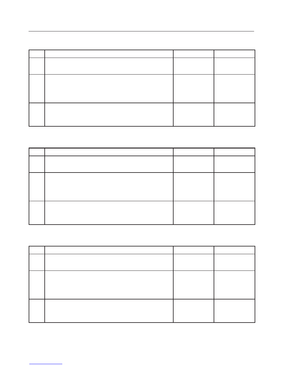
Chart B-10 EHCU Valve Relay Failure (DTC 35 (Flash out) / C0265, C0266 (Serial
communications))
Step
Action
Yes
No
1
1. Turn the key off.
2. Disconnect coil integrated module connector.
3. Measure the voltage between terminal 1 of the coil integrated
module connector (C-5) and body ground.
Is the voltage equal to the battery voltage?
Replace EHCU.
Go to Step 2
Repair fuse and
harness coil
integrated
module connector
(C-5) terminal 1
and battery.
Go to Step 2
2
1. Reconnect all components, ensure all components are
properly mounted.
2. Clear diagnostic trouble code.
Was this step finished?
Repeat the “Basic
diagnostic flow
chart”
Go to Step 2
Chart B-11 FL Isolation Solenoid Coil Failure (DTC 41 (Flash out) / C0245, C0247 (Serial
communications))
Step
Action
Yes
No
1
Was the “EHCU Connector Pin–out Checks” performed?
Go to Step 2
Go to “EHCU
Connector
Pin–out Checks.”
2
1. Turn the key switch to off.
2. Disconnect the 2–way EHCU connector (C–5) from the
EHCU.
3. Inspect the connector for damage or corrosion.
Is the connector free from damage or corrosion?
Go to Step 3
Repair the
connector.
Repeat the “Basic
Diagnostic Flow
Chart.”
3
1. Replace the Coil Integrated Module.
2. Reconnect all component, ensure all components are properly
mounted.
Was this step finished?
Repeat the “Basic
diagnostic flow
chart”
Go to Step 3
Chart B-12 FL Dump Solenoid Coil Failure (DTC 42 (Flash out) / C0246, C0248 (Serial
communications))
Step
Action
Yes
No
1
Was the “EHCU Connector Pin–out Checks” performed?
Go to Step 2
Go to “EHCU
Connector
Pin–out Checks.”
2
1. Turn the key switch to off.
2. Disconnect the 2–way EHCU connector (C–5) from the
EHCU.
3. Inspect the connector for damage or corrosion.
Is the connector free from damage or corrosion?
Go to Step 3
Repair the
connector.
Repeat the “Basic
Diagnostic Flow
Chart.”
3
1. Replace the Coil Integrated Module.
2. Reconnect all component, ensure all components are properly
mounted.
Was this step finished?
Repeat the “Basic
diagnostic flow
chart”
Go to Step 3
5A–45
BRAKE CONTROL SYSTEM
Chart B-13 FR Isolation Solenoid Coil Failure (DTC 43 (Flash out) / C0241, C0243 (Serial
communications))
Step
Action
Yes
No
1
Was the “EHCU Connector Pin–out Checks” performed?
Go to Step 2
Go to “EHCU
Connector
Pin–out Checks.”
2
1. Turn the key switch to off.
2. Disconnect the 2–way EHCU connector (C–5) from the
EHCU.
3. Inspect the connector for damage or corrosion.
Is the connector free from damage or corrosion?
Go to Step 3
Repair the
connector.
Repeat the “Basic
Diagnostic Flow
Chart.”
3
1. Replace the Coil Integrated Module.
2. Reconnect all component, ensure all components are properly
mounted.
Was this step finished?
Repeat the “Basic
diagnostic flow
chart”
Go to Step 3
Chart B-14 FR Dump Solenoid Coil Failure (DTC 44(Flash out) / C0242, C0244 (Serial
communications))
Step
Action
Yes
No
1
Was the “EHCU Connector Pin–out Checks” performed?
Go to Step 2
Go to “EHCU
Connector
Pin–out Checks.”
2
1. Turn the key switch to off.
2. Disconnect the 2–way EHCU connector (C–5) from the
EHCU.
3. Inspect the connector for damage or corrosion.
Is the connector free from damage or corrosion?
Go to Step 3
Repair the
connector.
Repeat the “Basic
Diagnostic Flow
Chart.”
3
1. Replace the Coil Integrated Module.
2. Reconnect all component, ensure all components are properly
mounted.
Was this step finished?
Repeat the “Basic
diagnostic flow
chart”
Go to Step 3
Chart B-15 Rear Isolation Solenoid Coil Failure (DTC 45 (Flash out) / C0251, C0253 (Serial
communications))
Step
Action
Yes
No
1
Was the “EHCU Connector Pin–out Checks” performed?
Go to Step 2
Go to “EHCU
Connector
Pin–out Checks.”
2
1. Turn the key switch to off.
2. Disconnect the 2–way EHCU connector (C–5) from the
EHCU.
3. Inspect the connector for damage or corrosion.
Is the connector free from damage or corrosion?
Go to Step 3
Repair the
connector.
Repeat the “Basic
Diagnostic Flow
Chart.”
3
1. Replace the Coil Integrated Module.
2. Reconnect all component, ensure all components are properly
mounted.
Was this step finished?
Repeat the “Basic
diagnostic flow
chart”
Go to Step 3
5A–46
BRAKE CONTROL SYSTEM
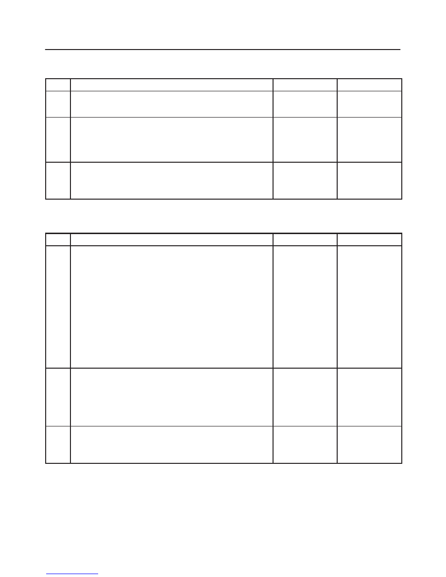
Chart B-16 Rear Dump Solenoid Coil Failure (DTC 46 (Flash out) / C0252, C0254 (Serial
communications))
Step
Action
Yes
No
1
Was the “EHCU Connector Pin–out Checks” performed?
Go to Step 2
Go to “EHCU
Connector
Pin–out Checks.”
2
1. Turn the key switch to off.
2. Disconnect the 2–way EHCU connector (C–5) from the
EHCU.
3. Inspect the connector for damage or corrosion.
Is the connector free from damage or corrosion?
Go to Step 3
Repair the
connector.
Repeat the “Basic
Diagnostic Flow
Chart.”
3
1. Replace the Coil Integrated Module.
2. Reconnect all component, ensure all components are properly
mounted.
Was this step finished?
Repeat the “Basic
diagnostic flow
chart”
Go to Step 3
Chart B-17 FL Speed Sensor Open or Shorted (DTC 51 (Flash out) / C0225 (Serial
communications))
Step
Action
Yes
No
1
1. Turn the key off.
2. Disconnect coil integrated module connector.
3. Measure the resistance between coil integrated module
connector (C-4) terminals 2 and 10.
Is the resistance between 2.0k and 2.8k ohms?
Check for faults
in harness
between speed
sensor and coil
integrated
module.
Fault found:
Repair, and
perform system
self-check.
No fault found:
Replace coil
integrated
module.
Go to Step 3
Go to Step 2
2
Measure the FL speed sensor resistance at the sensor connector.
Is the resistance between 2.0k and 2.8k ohms?
Repair harness
abnormality
between sensors
and coil
integrated
module.
Go to Step 3
Replace sensor.
Go to Step 3
3
1. Reconnect all components, ensure all components are
properly mounted.
2. Clear diagnostic trouble code.
Was this step finished?
Repeat the “Basic
diagnostic flow
chart”
Go to Step 3
Нет комментариевНе стесняйтесь поделиться с нами вашим ценным мнением.
Текст