Isuzu Rodeo UE. Manual — part 103
5A–35
BRAKE CONTROL SYSTEM
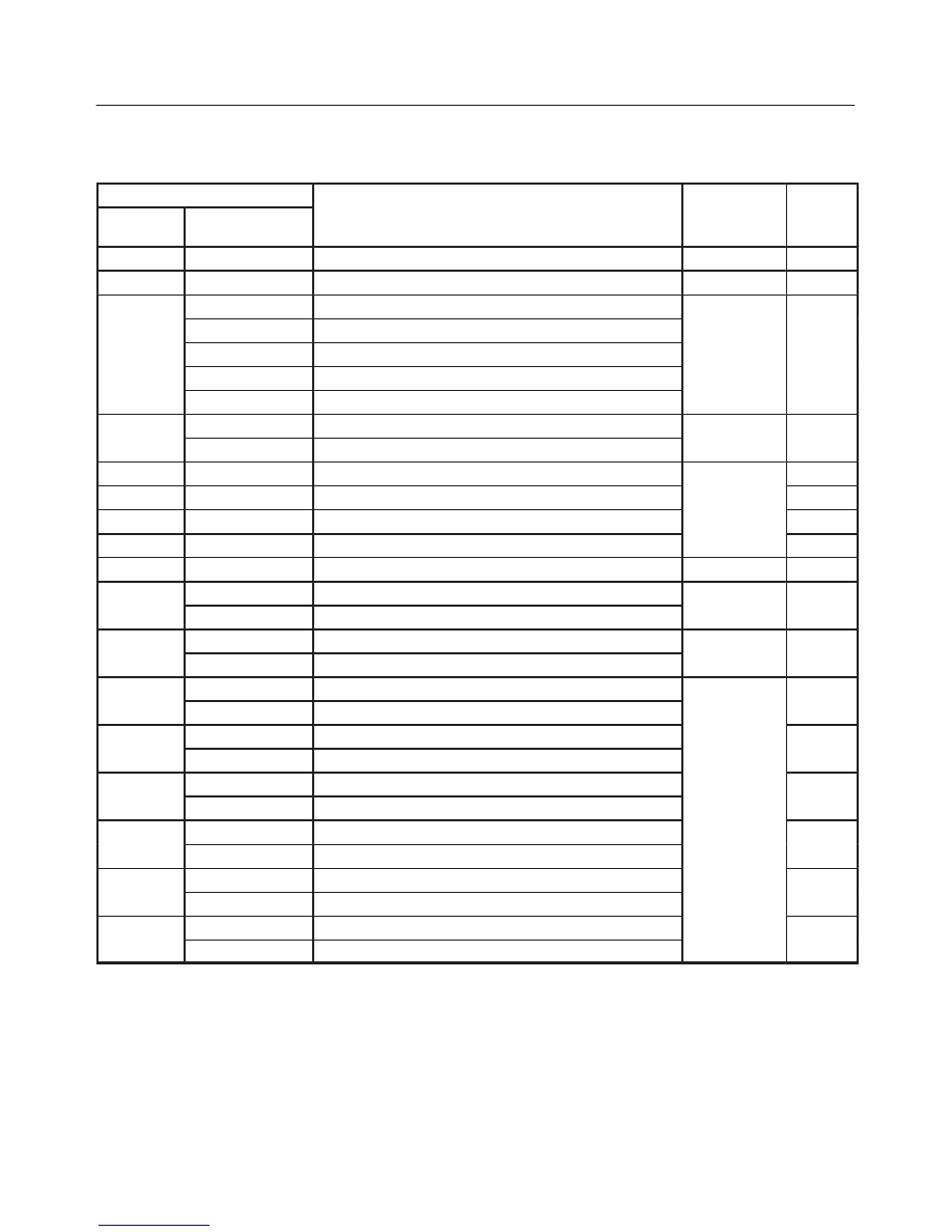
Diagnostic Trouble Codes
Choose and trace an appropriate flowchart by the
numbers listed below to find fault and repair.
Code
Chart
Flash out
Serial
Communications
Diagnosis
Item
Chart
No.
12
—
—
—
—
13
C0285
2 WD Controller in 4WD Vehicle Controller
Wiring
B-8
14
C0271
RAM read/write error
C0272
ROM checksum error
Coil
C0270
ALU function error
Coil
Integrated
M d l
B-2
C0273
Inoperative isolation item
Module
C0284
Loop time overrun
15
C0277
Low ignition voltage
Wiring
B-3
C0278
High ignition voltage
Wiring
B-3
17
C0269
Excessive dump time
B-4
18
C0274
Excessive isolation time
Coil
Integrated
B-5
21
C0276
G-Sensor Failure
Integrated
Module
B-6
22
C0281
Brake switch Failure
B-7
24
C0282
Open or shorted 4
×
4 input signal (4WD only)
Wiring
B-8
32
C0267
Open motor circuit or shorted ECU output
Motor
B-9
C0268
Stalled motor or open ECU output
Motor
B-9
35
C0265
Open relay circuit
Relay
B-10
C0266
Shorted relay circuit
Relay
B-10
41
C0245
FL Open isolation solenoid or shorted ECU output
B-11
C0247
FL Shorted isolation solenoid or open ECU output
B-11
42
C0246
FL Open dump solenoid or shorted ECU output
B-12
C0248
FL Shorted dump solenoid or open ECU output
B-12
43
C0241
FR Open isolation solenoid or shorted ECU output
B-13
C0243
FR Shorted isolation solenoid or open ECU output
Solenoid
B-13
44
C0242
FR Open dump solenoid or shorted ECU output
Solenoid
B-14
C0244
FR Shorted dump solenoid or open ECU output
B-14
45
C0251
Rear Open isolation solenoid or shorted ECU output
B-15
C0253
Rear Shorted isolation solenoid or open ECU output
B-15
46
C0252
Rear Open dump solenoid or shorted ECU output
B-16
C0254
Rear Shorted dump solenoid or open ECU output
B-16
5A–36
BRAKE CONTROL SYSTEM
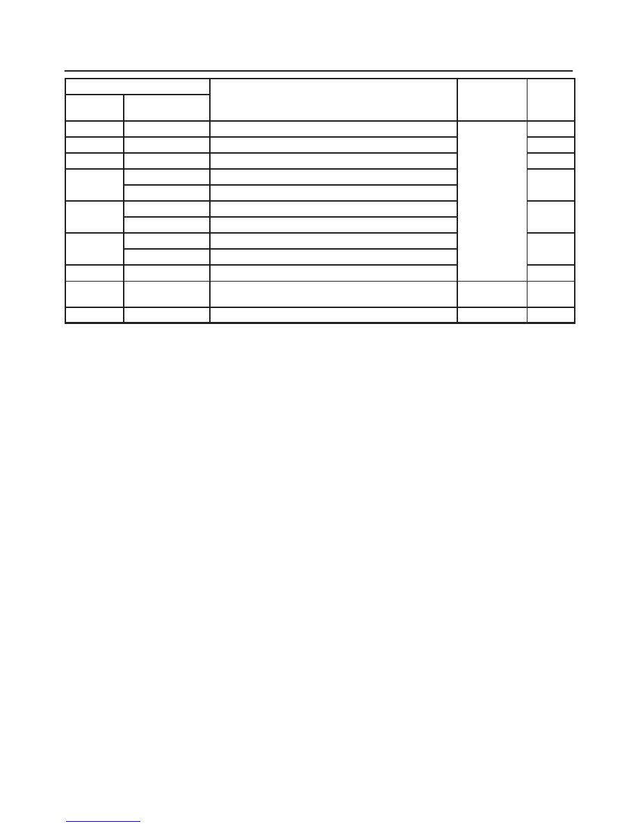
Code
Chart
Flash out
Serial
Communications
Diagnosis
Item
Chart
No.
51
C0225
FL Open or shorted sensor
B-17
52
C0221
FR Open or shorted sensor
B-18
53
C0235
Rear Open or shorted sensor
B-19
61
C0226
FL Missing sensor signal
B-20
C0227
FL Sensor signal dropout
Sensor or
B-20
62
C0222
FR Missing sensor signal
Wiring
B-21
C0223
FR Sensor signal dropout
B-21
63
C0236
Rear Missing sensor signal
B-22
C0237
Rear Sensor signal dropout
B-22
64
C0229
Simultaneous dropout of front sensor signal
B-23
65
C0238
Wheel speed error
Vehicle or
Sensor
B-24
—
C0286
Shorted indicator lamp
Wiring
—
5A–37
BRAKE CONTROL SYSTEM
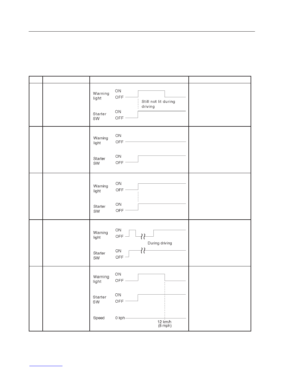
Diagnosis By “ABS” Warning Light
Illumination Pattern
In the event that there is abnormality in the “ABS” warning
light illumination pattern while the key is in the ON position
or if the warning light is actuated during driving, trouble
should be diagnosed on a illumination pattern basis as
follows:
No.
Condition
“ABS” Warning Light Illumination Pattern
Diagnostic
1
Warning light is actu-
ated normally
Normal
2
Warning light is not lit
Warning light lighting circuit
trouble
→
Go to Chart B-1
3
Warning light remains
ON
Diagnostic trouble codes are
stored.
Display diagnostic trouble
codes and diagnose on a
code basis according to the
flow charts.
4
Warning light is actu-
ated while driving
Diagnostic trouble codes are
stored.
Display diagnostic trouble
codes and diagnose on a
code basis according to the
flow charts.
5
Warning light goes at
12 km/h (8 mph) or
higher (After repairing
the faulty part)
Even after repairing the
faulty part the warning light
(W/L) dose not go out it ve-
hicle is at a stop.
Turn the ignition switch to the
ON position and drive the ve-
hicle at 12 km/h (8 mph) or
higher to make sure that the
warning light goes out.
5A–38
BRAKE CONTROL SYSTEM
Diagnostic Trouble Codes (DTCs)
When the warning light in the meter remains ON, the
EHCU stores the fault identification and disables the
ABS.
How to display and erase DTCs:
NOTE:
f
DTCs can be displayed also by TECH 2. Use
“Diagnostic Trouble Codes” mode.
1. How to start DTC display:
f
Confirm that the vehicle has come to a complete
stop (with the wheels standing still) and that the
brake pedal is not depressed. (Unless these two
condition are satisfied, DTC display cannot be
started.)
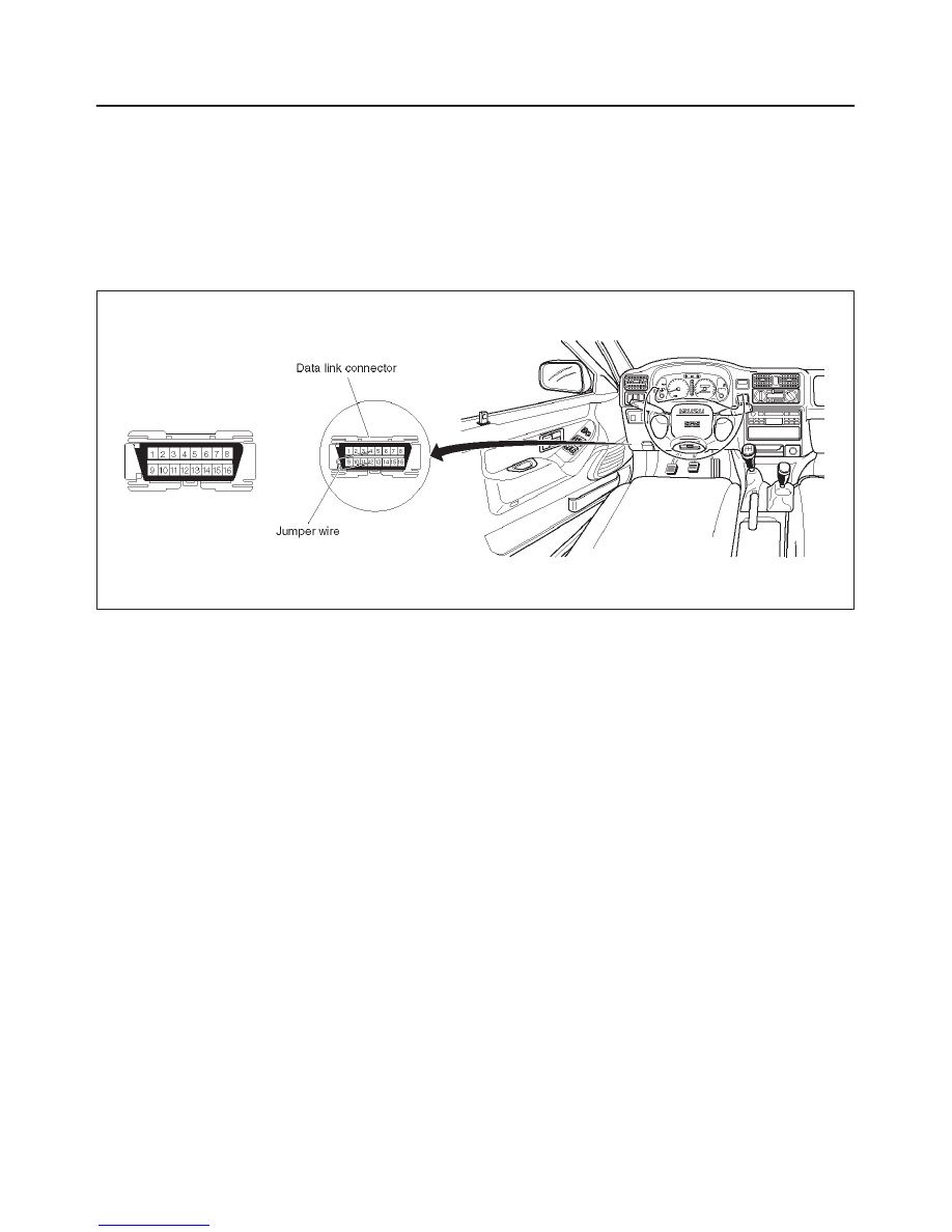
f
With IGN OFF, connect #12 terminal with #4
terminal or # 5 terminal (GND) . Then turn IGN ON.
The DLC is located behind the driver side kick panel
350RW016
f
Keep #12 terminal connected with #4 terminal or # 5
terminal (GND) during DTC display. (If #12 terminal
is separated from #4 terminal or # 5 terminal (GND)
during display, display will stop.)
2. DTC display:
f
DTC is displayed by blinking warning light.
f
Double-digit display.
f
First, normal DTC 12 is displayed three times and
then any other DTCs are displayed three times. (If
no other DTCs have been stored, the display of DTC
12 will be repeated.)
3. How to erase code:
f
Conduct brake switch ON/OFF operation 6 or more
times within 3 seconds of self-diagnosis startup.
f
The code cannot be erased if more than 3 seconds
have passed since self-diagnosis startup, or if
self-diagnosis has started with brake switched on
(brake pedaled).
Нет комментариевНе стесняйтесь поделиться с нами вашим ценным мнением.
Текст