Isuzu Rodeo UE. Manual — part 508
7B–64
MANUAL TRANSMISSION
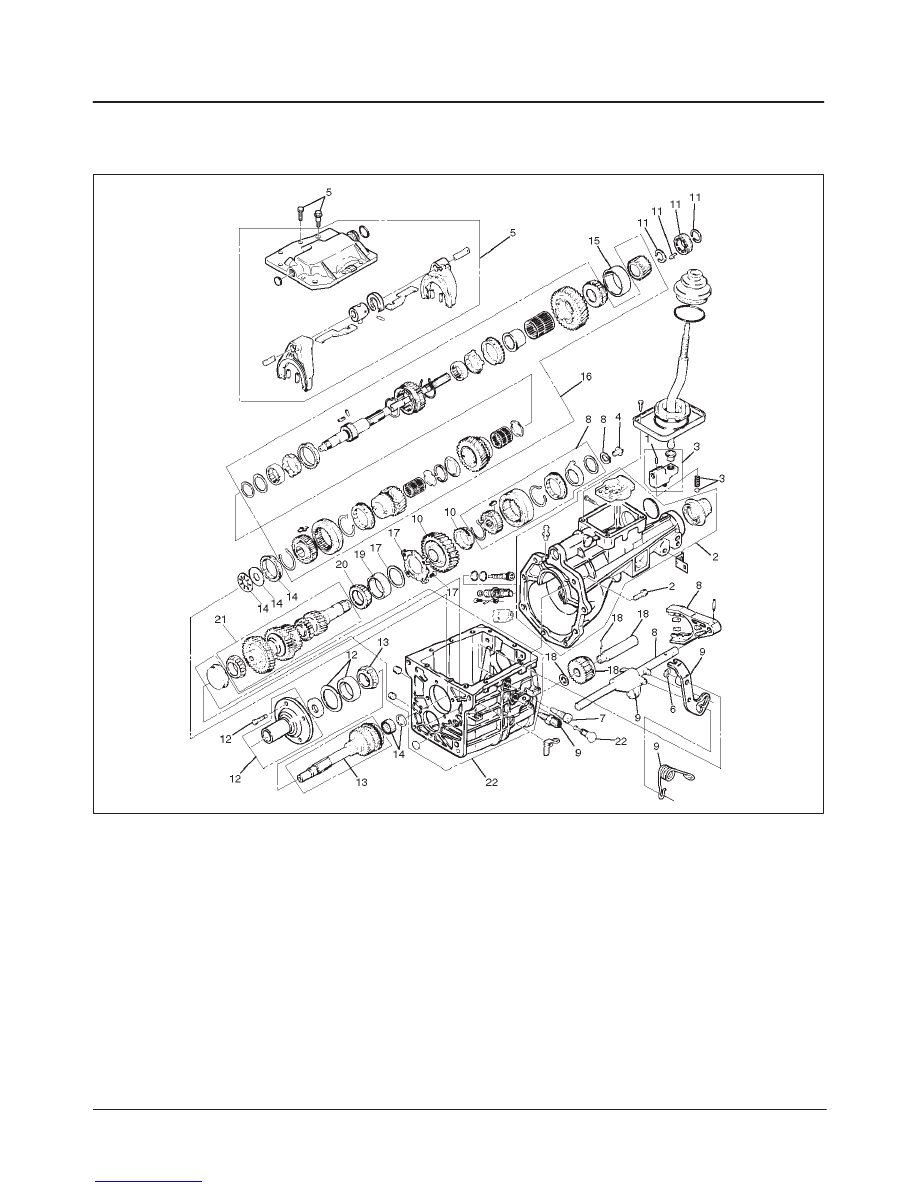
Transmission Case (TREMEC T5R)
Disassembled View
220RW061
Legend
(1) Offset Lever Roll Pin
(2) Extension Housing Assembly
(3) Offset Lever, Detent Ball and Spring
(4) Oiling Funnel
(5) Shift Cover Assembly
(6) 5–R shift Lever Clip
(7) 5–R Lever Pivot Bolt
(8) 5th Synchronizer Snap Ring, Splined Washer,
Revers Cone, Reverse Blocking Ring, 5th
Synchronizer, 5th Shift Fork and Rail
(9) 5–R Shift Lever, Reverse Fork and Spring
(10) 5th Drive Gear and 5th Synchronizer Blocking
Ring
(11) Slip Yoke Seal, Snap Ring, Speedometer Drive
Gear and Clip, and 5th Driven Gear Snap Ring
(12) Input Shaft Bearing Retainer, Bearing Outer
Race and Shim(s)
(13) Input Shaft Assembly
(14) 4th Gear Blocking Ring, Mainshaft Thrust
Bearing and Race, Mainshaft Needle Bearing
(15 Rollres) and Spacer
(15) Mainshaft Rear Bearing Outer Race
(16) Mainshaft Assembly
(17) Counter Shaft Rear Bearing Retainer and Shim
(18) Reverse Idler Shaft Roll Pin, Reverse Idler
Shaft, Reverse Idler Gear and O-ring
(19) Counter Shaft Rear Bearing Outer Race
(20) Counter Shaft Rear Bearing
(21) Counter Shaft Assembly
(22) Transmission Case
MANUAL TRANSMISSION
7B–65
Disassembly
1. Clean the exterior of the unit with solvent.
2. Remove the clutch release bearing and shift fork.
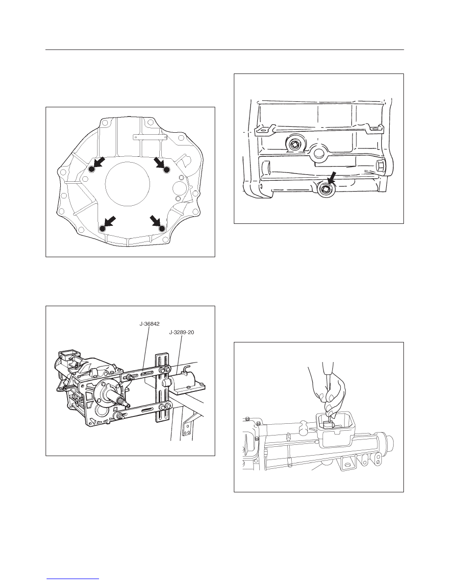
3. Remove the 4 bolts that hold the clutch housing to the
case.
F07RW004
4. Mount the transmission in the holding fixture
J–36842.
Install the transmission with its holding fixture into the
holding fixture base J–3289–20 mounted on the end
of a work bench.
220RS052
5. Remove the drain plug from the transmission case
and drain the lubricant.
220RS053
6. Remove the speedometer driven gear assembly,
using a 10 mm wrench to remove the clamp bolt.
Pull out the sleeve/gear.
7. Position the offset lever(3) in the “3–4” neutral
position.
NOTE: Removal of the offset lever in a position other than
“3–4” may result in driving a roll pin(1) into the
detent/guide plate without releasing the lever(3) from the
shift shaft. Further disassembly will be difficult if this
occurs.
8. Using a 3/16–inch diameter pin punch and a hammer,
remove the offset lever roll pin(1) attaching the offset
lever to the shift shaft.
220RW058
7B–66
MANUAL TRANSMISSION
9. Remove the 8 bolts that hold the extension housing to
the case, using a 15 mm wrench.
Note that two bolts use sealer.
Separate the extension housing assembly(2) from
the case and shift cover. The offset lever(3) will also
separate from the shift shaft.
NOTE: Do not attempt to remove the offset lever while
the extension housing is still bolted to the case. The lever
has a positioning lug which engages the detent/guide
plate and prevents moving the lever far enough to remove
it.
220RW059
10. Remove the offset lever(3) from the extension
housing, along with the detent ball(3) and spring(3).
Remove the roll pin(1) from either the offset lever or
extension housing.
230RS014
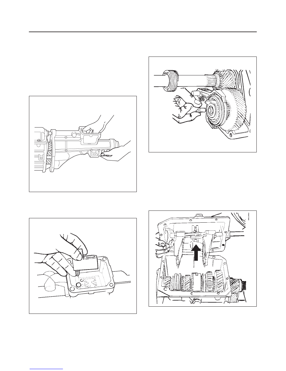
11. Carefully pry the oiling funnel(4) from the rear of the
counter shaft. This may be a very snug fit, and the
funnel may become damaged during removal unless
extreme care is used.
226RS097
12. Remove the 10 bolts that hold the shift cover to the
case, using a 10 mm wrench.
NOTE: Two of the shift cover bolts are also alignment
dowels. Note the location of these bolts for assembly.
Remove the shift cover assembly(5) from the case by
sliding it sideways toward the drain plug side of the
case for a distance of 1 inch. Then lift the cover
straight up from the case. You may need to break the
sealer bond between the cover and case before you
can separate them.
230RS015

MANUAL TRANSMISSION
7B–67
13. Remove the 5–R shift lever clip(6), using a pair of
needlenose pliers.
230RS016
14. Remove the 5–R lever pivot bolt(7), using a T–50 bit
and ratchet. Note that this bolt uses sealer.
230RS017
15. Remove the 5th synchronizer snap ring(8) from the
rear of the counter shaft, using a pair of snap ring
pliers.
226RS098
Remove splined washer(8), reverse cone(8) and
reverse blocking ring(8).
Remove the 5th synchronizer assembly(8), together
with its fork/rail assembly(8), from the counter shaft.
226RS099
Нет комментариевНе стесняйтесь поделиться с нами вашим ценным мнением.
Текст