Isuzu Rodeo UE. Manual — part 102

5A–31
BRAKE CONTROL SYSTEM
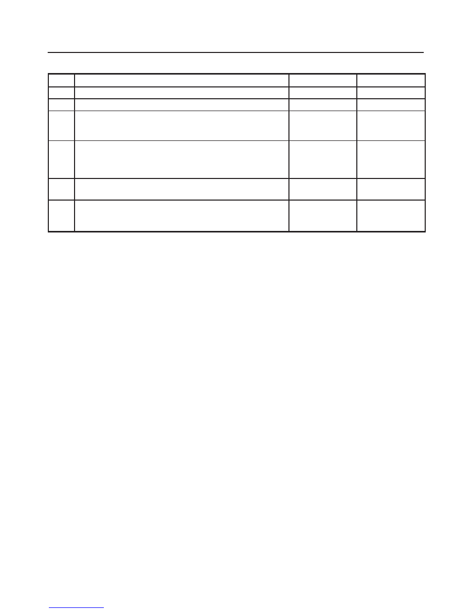
Chart TA-1 ABS Works Frequently But Vehicle Does Not Decelerate (Use TECH 2)
Step
Action
Yes
No
1
1. Connect TECH 2.
2. Make sure of the output conditions of each sensor.
Is the output of each sensor normal?
Go to Step 2
Replace wheel
speed sensor.
Go to Step 3
2
Return to Chart A-1.
Was the Chart A-1 finished?
Go to Step 3
Go to Step 2
3
Reconnect all components, ensure all components are properly
mounted.
Was this step finished?
Repeat the “Basic
diagnostic flow
chart”
Go to Step 3
Chart A-2 Uneven Braking Occurs While ABS Works
Step
Action
Yes
No
1
Is there play in each or any sensor?
Repair.
Go to Step 5
Go to Step 2
2
Damage or powdered iron sticking to each or any sensor/sensor
ring?
Repair.
Go to Step 5
Go to Step 3
3
Is the output of each sensor normal? (Refer to chart C-1 or TC-1)
Go to Step 4
Replace sensor
or repair harness.
Go to Step 5
4
Is brake pipe connecting order correct?
Replace H/U.
Go to Step 5
Reconnect brake
pipe correctly.
Go to Step 5
5
Reconnect all components, ensure all components are properly
mounted.
Was this step finished?
Repeat the “Basic
diagnostic flow
chart”
Go to Step 5
Chart TA-2 Uneven Braking Occurs While ABS Works (Use TECH 2)
Step
Action
Yes
No
1
1. Connect TECH 2.
2. Make sure of the output conditions of each sensor.
Is the output of each sensor normal?
Go to Step 2
Go to Step 3
2
Check piping by TECH 2 ACTUATOR TEST
Is the piping normal?
Replace EHCU.
Go to Step 4
Repair the pipe.
Go to Step 4
3
Repair and check the wheel speed sensor (Refer to chart B-20 to
B-23 , C-1 or TC-1).
Was the each chart finished?
Go to Step 4
Go to Step 3
4
Reconnect all components, ensure all components are properly
mounted.
Was this step finished?
Repeat the “Basic
diagnostic flow
chart”
Go to Step 4
5A–32
BRAKE CONTROL SYSTEM
Chart A-3, TA-3 The Wheels Are Locked
Step
Action
Yes
No
1
Is ABS working?
Go to Step 2
Go to Step 6
2
Is vehicle speed under 10 km/h (6mph)?
Normal.
Go to Step 3
3
Is sensor output normal? (Chart C-1 or TC-1)
Go to Step 4
Replace sensor
or repair harness.
Go to Step 6
4
Is front 4WD controller normal?
Go to Step 5
Replace 4WD
controller or
repair harness.
Go to Step 6
5
Is hydraulic unit grounded properly?
Replace EHCU.
Go to Step 6
Correct.
Go to Step 6
6
Reconnect all components, ensure all components are properly
mounted.
Was this step finished?
Repeat the “Basic
diagnostic flow
chart”
Go to Step 6

5A–33
BRAKE CONTROL SYSTEM
Chart A-4 Brake Pedal Feed Is Abnormal
Step
Action
Yes
No
1
Is the stop light actuated when the brake pedal is depressed?
Go to Step 2
Go to Step 3
2
1. Turn the ignition switch off.
2. Disconnected EHCU connector.
Is the check voltage EHCU connector terminals 13 to 7 when
brake pedal is depressed than battery voltage?
Go to Step 4
Harness NG
between brake
SW and EHCU.
Go to Step 6
3
Is stop light fuse normal?
Go to Step 5
Replace stop light
fuse.
Go to Step 6
4
Is the check continuity between EHCU connector terminals, 7 to
body grounded?
Go to Step 6
Repair body
grounded
harness.
Go to Step 6
5
Is brake SW normal?
Repair stop light
harness.
Go to Step 6
Replace brake
SW.
Go to Step 6
6
Reconnect all components, ensure all components are properly
mounted.
Was this step finished?
Repeat the “Basic
diagnostic flow
chart”
Go to Step 6

5A–34
BRAKE CONTROL SYSTEM
Chart A-5, TA-5 Braking Sound (From EHCU) Is Heard While Not Braking
Step
Action
Yes
No
1
Is this the first vehicle start after engine start?
It is self checking
sound
Normal.
Go to Step 2
2
Is vehicle speed under 10 km/h (6 mph)?
It is self checking
sound
Normal.
Go to Step 3
3
Check for the following condition:
f
At the time of shift down or clutch operation.
f
At the time of low road friction drive (ice or snow road) or rough
road drive.
f
At the time of high-speed turn.
f
At the time of passing curb.
f
At the time of operating electrical equipment switches.
f
At the time of racing the engine (over 5000 rpm).
Did it occur under any one condition above?
ABS may
sometime be
actuated even
when brake pedal
is not applied.
Go to Step 4
4
Is there play in each or any sensor/wheel speed sensor rings?
Repair.
Go to Step 7
Go to Step 5
5
Damage or powdered iron sticking to each or any sensor/wheel
speed sensor ring?
Repair.
Go to Step 7
Go to Step 6
6
Is each sensor output normal? (Refer to chart C-1 or TC-1).
Check harness/
connector for
suspected
disconnection
If no
disconnection is
found, replace
Coil integrated
module.
Go to Step 7
Repair.
Go to Step 7
7
Reconnect all components, ensure all components are properly
mounted.
Was this step finished?
Repeat the “Basic
diagnostic flow
chart”
Go to Step 7
Нет комментариевНе стесняйтесь поделиться с нами вашим ценным мнением.
Текст