Isuzu Rodeo UE. Manual — part 53

4A1–3
DIFFERENTIAL (FRONT)
Pinion Shaft Oil Seal
Pinion Shaft Oil Seal and Associated Parts
415RW012
Legend
(1) Flange Nut
(2) Flange
(3) Oil Seal
(4) Oil Seal Slinger
(5) Outer Bearing
(6) Collapsible Spacer
Removal
1. Raise the vehicle and support it at the frame.
The hoist must remain under the front axle housing.
2. Drain the front axle oil by loosening the drain plug(1).
412RS001
DIFFERENTIAL (FRONT)
4A1–4
3. Remove the front propeller shaft. Refer to Front
Propeller Shaft in this section.
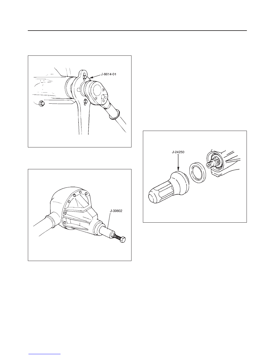
4. Remove flange nut by using pinion flange holder
J–8614–01.
415RS018
5. Remove flange.
6. Remove oil seal.
7. Remove outer bearing by using remover J–39602.
415RS001
8. Remove collapsible spacer.
Inspection and Repair
Make necessary correction or parts replacement if wear,
damage, corrosion or any other abnormal condition are
found through inspection.
Check the following parts.
1. Seal surface of the pinion.
2. Cage bore for burns.
Installation
1. Install collapsible spacer. Discard the used
collapsible spacer and install a new one.
2. Install outer bearing.
NOTE: Do not drive in, but just temporarily set in the outer
bearing by hand, which should be indirectly pressed in
finally by tightening the flange nut.
3. Install oil seal, use oil seal installer J–24250 to install a
new oil seal that has grease on seal lip.
415RS002
4. Install flange.
5. Install flange nut, refer to Differential Assembly
Overhaul for flange nut reassembly in this section.
NOTE: Discard the used nut and install a new one.
4A1–5
DIFFERENTIAL (FRONT)
Front Drive Axle Assembly
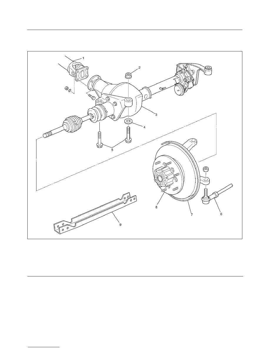
Front Drive Axle Assembly and Associated Parts
412RW056
Legend
(1) Propeller Shaft
(2) Mounting Nut
(3) Front Axle Case Assembly and Front Drive
Shaft Assembly
(4) Washer
(5) Mounting Bolt
(6) Tie–rod End; Power Steering Unit
(7) Knuckle and Back Plate
(8) Hub and Disc Assembly
(9) Suspension Crossmember
DIFFERENTIAL (FRONT)
4A1–6
Removal
1. Jack up the vehicle and support it using jack stand.
2. Remove the tire and wheel.
3. Remove the stone guard.
4. Remove the brake caliper fixing bolt and hang the
caliper. Refer to Disc Brakes in Brake section.
5. Remove the antilock brake system speed sensor.
Refer to Front Wheel Speed Sensor in Brake section.
6. Remove the hub and disc assembly.
Refer to Front Hub and Disc in this section.
7. Remove the propeller shaft, refer to Front Propeller
Shaft in this section.
8. Loosen the height control arm of the torsion bar, then
remove the torsion bar from lower control arm.
refer to Torsion Bar in Suspension section.
9. Remove the suspension crossmember.
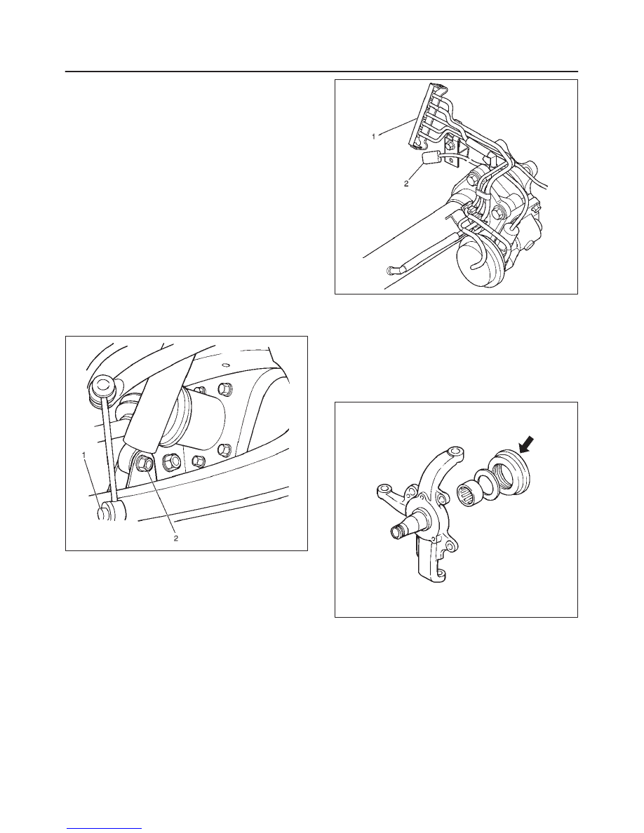
10. Remove the lower nut (1) of the stabilizer link.
11. Remove the lower bolt and nut (2) of the shock
absorber.
412RW057
12. Remove the tie-rod end from the knuckle. Refer to
Power Steering Unit in Steering Section.
13. Disconnect the hose of the shift on the fly, at the hose
clip portion (1).
14. Disconnect the shift switch connector (2).
412RW058
15. Remove the bolts and nuts of the lower control arm
(Frame side), then disconnect the lower control arm
from frame.
16. Disconnect between the right side upper control arm
and the knuckle, then remove the knuckle with lower
control arm.
CAUTION: When removing the knuckle, be careful
not to damage the oil seal inside of the knuckle.
410RW008
Нет комментариевНе стесняйтесь поделиться с нами вашим ценным мнением.
Текст