Isuzu Rodeo UE. Manual — part 54
4A1–7
DIFFERENTIAL (FRONT)
17. Support the differential case by the jack.
18. Remove the front axle mounting bolts and nuts, lower
the jack slowly. Remove the left side drive shaft end
from the knuckle, then lower the axle assembly from
the vehicle.
CAUTION:
1. During the work, be sure that the axle assembly is
supported securly.
2. Be careful not to damage the bellows of the power
steering unit by interference.
3. Be careful not to damage the hose bracket of the
shift on the fly by interference.
Installation
1. Support the differential case by the jack.
2. Jack up the front drive axle assembly, install the left
side drive shaft to the knuckle, then install the mount
bolts and nuts.
CAUTION:
1. Be careful not to damage the bellows of the power
steering unit by interference.
2. Be careful not to damage the hose bracket of the
shift on the fly by interference.
3. When installing the drive shaft to the knuckle, be
careful not to damage the oil seal inside of the
knuckle.
3. Tighten the mounting bolts and nuts to the specified
torque.
Torque: 168 N·m (124 lb ft)
412RW064
4. Install the right side knuckle with lower control arm to
the upper control arm.
Refer to Knuckle in Suspension section.
CAUTION: When insert the drive shaft to the
knuckle, be careful not to damage the oil seal inside
of the knuckle.
5. Align the bolt hole of the lower control arm, install the
bolts and nuts.
NOTE: Adjust the buffer clearance before tighten the
bolts and nuts of the lower control arm.
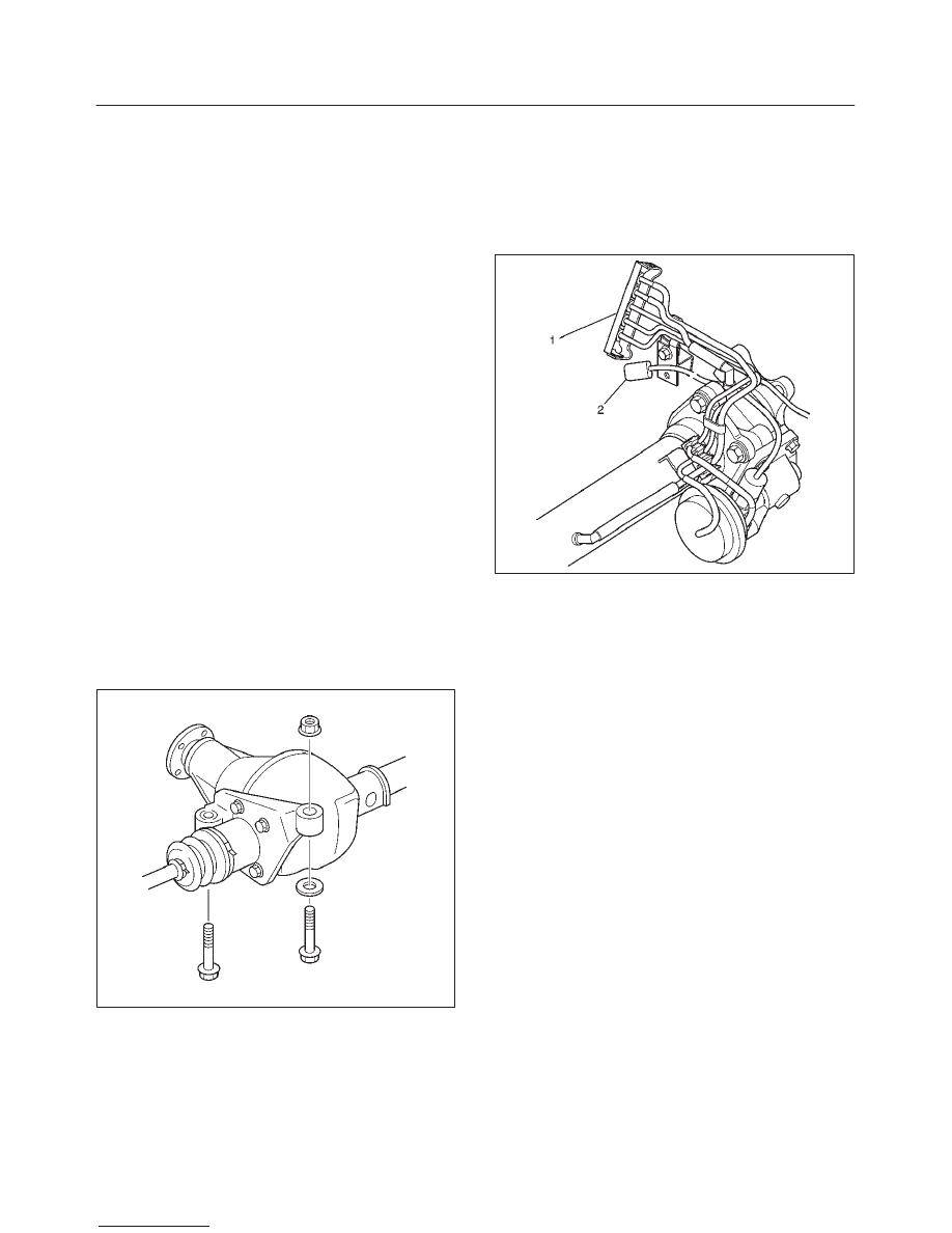
6. Install the hose of the shift on the fly (1).
7. Install the shift switch connector (2) of the shift on the
fly.
412RW058
8. Install the tie-rod end of the power steering unit to the
knuckle, tighten the nut to the specified torque.
Torque: 118 N·m (87 lb ft)
9. Install lower bolts and nuts of the shock absorber,
tighten it to the specified torque.
Torque: 93 N·m (69 lb ft)
10. Install lower nuts of the stabilizer link, tighten it to the
specified torque.
11. Install the suspension crossmember.
12. Install the torsion bar.
Refer to Torsion Bar in Suspension section.
13. Install the front propeller shaft.
Refer to Front Propeller Shaft in this section.
14. Install the hub and disc assembly and adjust the
bearing preload.
Refer to Front Hub and Disc in this section.
15. Install the wheel speed sensor of the antilock brake
system.
16. Install the brake caliper. Tighten the bolt of the caliper
bracket to the specified torque.
Torque: 50 N·m (37 lb ft)
17. Install the stone guard.
18. Install the tire and wheel.
19. Lower the vehicle, adjust the trim height.
Refer to Trim Height Adjustment in Steering section.
20. Tighten the bolts and nuts of the lower control arm to
the specified torque.
Refer to Lower Control Arm in Suspension section.
DIFFERENTIAL (FRONT)
4A1–8
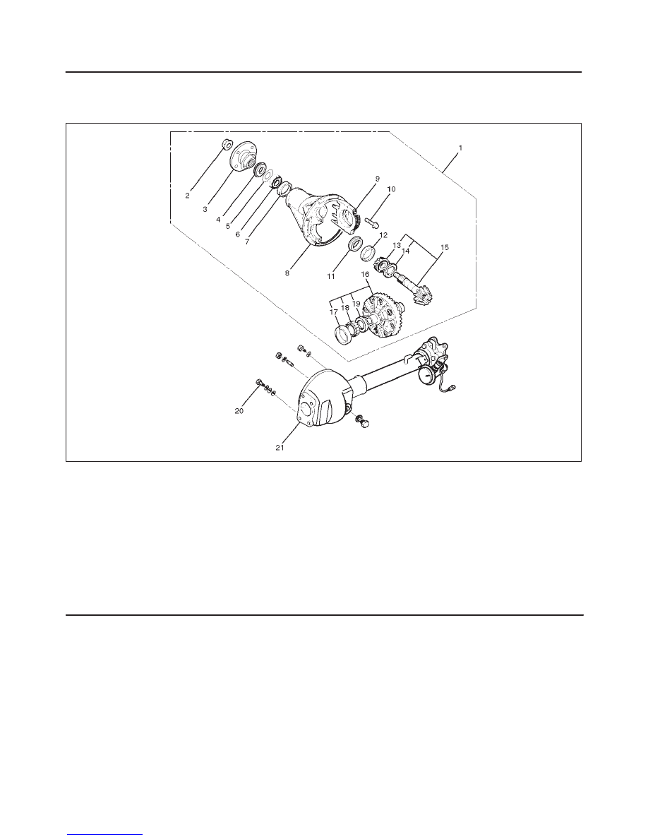
Differential Assembly
Disassembled View
415RW007
Legend
(1) Differential Assembly
(2) Flange Nut
(3) Flange
(4) Oil Seal
(5) Oil Seal Slinger
(6) Outer Bearing
(7) Outer Bearing Outer Race
(8) Differential Carrier
(9) Bearing Cap
(10) Bolt
(11) Collapsible Spacer
(12) Inner Bearing Outer Race
(13) Inner Bearing
(14) Adjust Shim
(15) Pinion Gear
(16) Diff Cage Assembly
(17) Side Bearing Outer Race
(18) Side Bearing
(19) Adjust Shim
(20) Bolt
(21) Axle Case
4A1–9
DIFFERENTIAL (FRONT)
Disassembly
1. Remove differential carrier fixing bolt.
2. Remove differential assembly.
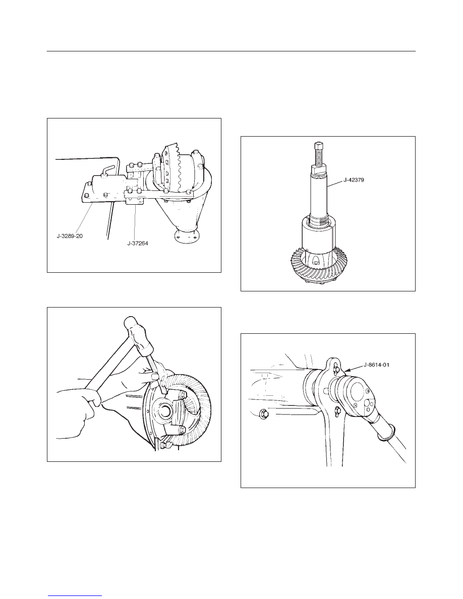
3. Using holding fixture J–37264 and holding fixture
base J–3289–20, fix the differential assembly to the
bench.
425RS008
4. Remove bearing cap bolt.
5. Apply a setting mark to the side bearing cap and the
differential carrier then remove bearing cap.
425RS009
6. Remove differential cage assembly.
7. Remove side bearing outer race, after removal, keep
the right and left hand side bearing assemblies
separate to maintain inner and outer race
combinations.
8. Remove side bearing, using remover J–42379 and
adapter J–8107–2.
f
Select insert; 303173 and collet halves; 44801 in
remover kit J–42379.
415RW003
9. Remove adjust shim, note the thickness and position
of the shims removed.
10. Remove the flange nut using holding wrench
J–8614–01.
415RS018

DIFFERENTIAL (FRONT)
4A1–10
11. Remove flange using an universal puller.
12. Remove the drive pinion assembly using a soft metal
rod and a hammer.
425RS012
13. Remove collapsible spacer.
14. Remove the inner bearing using remover J–42379.
f
Select insert; 303173 and collet halves; 44801 in
remover kit J–42379.
415RW004
15. Remove adjust shim.
16. Remove oil seal.
17. Remove oil seal slinger.
18. Remove outer bearing.
19. Remove the inner bearing outer race (1) and the outer
bearing outer race (2) by using a brass bar and a
hammer.
425RS014
425RS015
Нет комментариевНе стесняйтесь поделиться с нами вашим ценным мнением.
Текст