Isuzu Rodeo UE. Manual — part 652
9J1–45
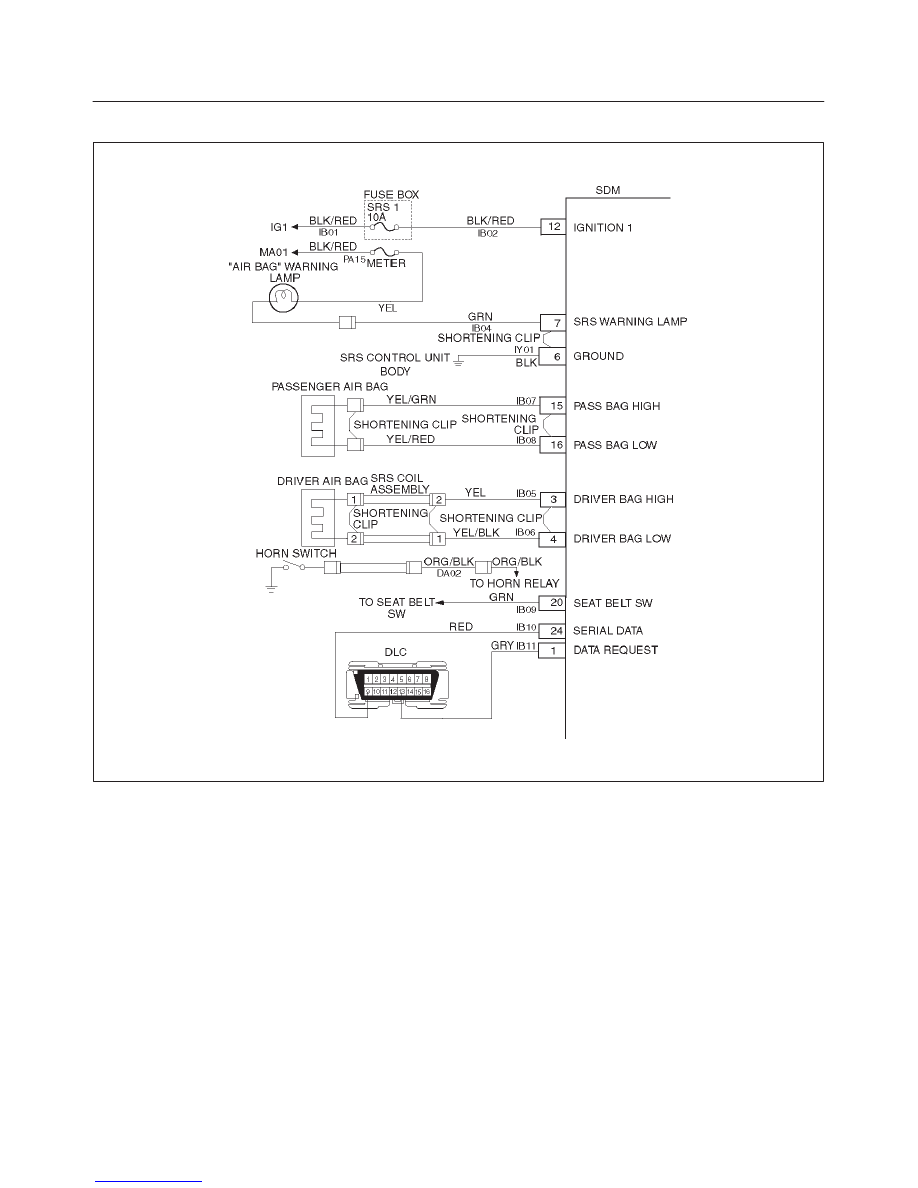
RESTRAINT CONTROL SYSTEM
DTC 71 Internal SDM Fault
D09RW002
Circuit Description:
DTC 71 is an indication of a potential internal SDM
malfunction and will set if any of the following conditions
are detected:
1) Deployment or microprocessor energy reserve failure.
2) EEPROM failure.
3) ROM failure.
4) RAM failure.
5) Calibration check sum failure.
6) Deployment switch faults.
7) Accelerometer fault.
8) Arming sensor fault.
9) Diagnostic current faults.
10) DTC 19
11) DTC 25
12) DTC 51
13) DTC 53
DTC Will Set When:
Any of the above indicated malfunctions are detected by
the SDM. The malfunctions described above are tested
mainly during “Continuous Monitoring” and some ones
run each ignition cycle.
Action Taken:
SDM turns “ON” the “AIR BAG” warning lamp and sets a
diagnostic trouble code.
DTC Will Clear When:
A scan tool “Clear Codes” commanded is received by the
SDM. Some of the indicated malfunctions will only allow
the “AIR BAG” warning lamp to go out.
But when DTC 19, 25, 51, 53 are also set, SDM is
Replaced.

RESTRAINT CONTROL SYSTEM
9J1–46
DTC 71 Internal SDM Fault
WARNING: DURING SERVICE PROCEDURES. BE VERY CAREFUL WHEN HANDLING A SENSING AND
DIAGNOSTIC MODULE (SDM). NEVER STRIKE OR JAR THE SDM. NEVER POWER UP THE SRS WHEN THE
SDM IS NOT RIGIDLY ATTACHED TO THE VEHICLE. ALL SDM AND MOUNTING BRACKET FASTENERS MUST
BE CAREFULLY TORQUED AND THE ARROW MUST BE POINTING TOWARD THE FRONT OF THE VEHICLE
TO ENSURE PROPER OPERATION OF THE SRS. THE SDM COULD BE ACTIVATED WHEN POWERED WHILE
NOT RIGIDLY ATTACHED TO THE VEHICLE WHICH COULD CAUSE DEPLOYMENT AND RESULT IN
PERSONAL INJURY.
CAUTION: When DTC 19 or 25 or 51 or 53 has been set it is necessary to Replace the SDM. Setting DTC 19 and
25 or 51 or 53 will also cause DTC 71 to set. When a scan tool “CLEAR CODES” command is issued and the
malfunction is no longer present, DTC 51 or 53 and DTC 71 will remain current. Ensure that the short to voltage
condition DTC 19, 25 is repaired prior to installing a Replacement SDM to avoid damaging the SDM.
Step
Action
Yes
No
1
Was the “SRS Diagnostic System Check” performed?
Go to Step 2
Go to the “SRS
Diagnostic
System Check.”
2
Note SRS “Diagnostic System Check.”
Is DTC 19 or 25 or 51 or 53 also set (current or history)? (Refer to
notice above).
Go to DTC 19 if
DTC 19 is set.
Go to DTC 25 if
DTC 25 is set.
Go to DTC 51 if
DTC 51 is set.
Go to DTC 53 if
DTC 53 is set.
Ignition switch
“OFF.”
Replace SDM.
Repeat the “SRS
Diagnostic
System Check.”
10A–1
CRUISE CONTROL SYSTEM
RODEO
CONTROL SYSTEM
CRUISE CONTROL SYSTEM
CONTENTS
Service Precaution
10A–1
. . . . . . . . . . . . . . . . . . . . . .
General Description
10A–1
. . . . . . . . . . . . . . . . . . . . .
Diagnosis
10A–2
. . . . . . . . . . . . . . . . . . . . . . . . . . . . . .
Brake Switch
10A–2
. . . . . . . . . . . . . . . . . . . . . . . . . . .
Removal and Installation
10A–2
. . . . . . . . . . . . . . .
Adjustment
10A–2
. . . . . . . . . . . . . . . . . . . . . . . . . . .
Clutch Switch
10A–3
. . . . . . . . . . . . . . . . . . . . . . . . . . .
Removal and Installation
10A–3
. . . . . . . . . . . . . . .
Adjustment
10A–3
. . . . . . . . . . . . . . . . . . . . . . . . . . .
Cruise Control Unit
10A–3
. . . . . . . . . . . . . . . . . . . . . .
Removal
10A–3
. . . . . . . . . . . . . . . . . . . . . . . . . . . . .
Installation
10A–3
. . . . . . . . . . . . . . . . . . . . . . . . . . . .
Cruise Actuator
10A–4
. . . . . . . . . . . . . . . . . . . . . . . . .
Actuator Cable Diagram
10A–4
. . . . . . . . . . . . . . . .
Removal
10A–4
. . . . . . . . . . . . . . . . . . . . . . . . . . . . .
Installation
10A–4
. . . . . . . . . . . . . . . . . . . . . . . . . . . .
Adjustment
10A–4
. . . . . . . . . . . . . . . . . . . . . . . . . . .
Mode Switch
10A–5
. . . . . . . . . . . . . . . . . . . . . . . . . . . .
Removal and Installation
10A–5
. . . . . . . . . . . . . . .
Cruise Control Main Switch
10A–5
. . . . . . . . . . . . . . .
Removal
10A–5
. . . . . . . . . . . . . . . . . . . . . . . . . . . . .
Installation
10A–5
. . . . . . . . . . . . . . . . . . . . . . . . . . . .
Cruise Control Switch (Combination Switch)
10A–6
Removal and Installation
10A–6
. . . . . . . . . . . . . . .
Service Precaution
WARNING: THIS VEHICLE HAS A SUPPLEMENTAL
RESTRAINT SYSTEM (SRS). REFER TO THE SRS
COMPONENT AND WIRING LOCATION VIEW IN
ORDER TO DETERMINE WHETHER YOU ARE
PERFORMING SERVICE ON OR NEAR THE SRS
COMPONENTS OR THE SRS WIRING. WHEN YOU
ARE PERFORMING SERVICE ON OR NEAR THE SRS
COMPONENTS OR THE SRS WIRING, REFER TO
THE SRS SERVICE INFORMATION. FAILURE TO
FOLLOW WARNINGS COULD RESULT IN POSSIBLE
AIR BAG DEPLOYMENT, PERSONAL INJURY, OR
OTHERWISE UNNEEDED SRS SYSTEM REPAIRS.
CAUTION: Always use the correct fastener in the
proper location. When you replace a fastener, use
ONLY the exact part number for that application.
ISUZU will call out those fasteners that require a
replacement after removal. ISUZU will also call out
the fasteners that require thread lockers or thread
sealant. UNLESS OTHERWISE SPECIFIED, do not
use supplemental coatings (Paints, greases, or other
corrosion inhibitors) on threaded fasteners or
fastener joint interfaces. Generally, such coatings
adversely affect the fastener torque and the joint
clamping force, and may damage the fastener. When
you install fasteners, use the correct tightening
sequence and specifications. Following these
instructions can help you avoid damage to parts and
systems.
General Description
The cruise control keeps the vehicle running at a fixed
speed until a signal canceling this fixed speed is received.
When the main switch “AUTO CRUISE” is turned on with
the vehicle in the running mode, the battery voltage is
applied to the control unit. When a signal from the control
switch is input to the control unit while the vehicle is in this
state, the cruise control actuator is activated to operate
the system. Also, while the system is operating, the
“AUTO CRUISE” indicator light in the meter assembly
lights up.
1 . SET/COAST Switch Function
1. Set Function: When the SET/COAST switch is
pressed and released with the main switch on, the
speed at which the vehicle is running at that moment
is stored in the memory, and the vehicle automatically
runs at the speed stored.
2. Coast–Down Function: When the SET/COAST
switch is kept on while the vehicle is running, the
vehicle decelerates during that time. The speed at
which vehicle is running when the control switch is
turned off is stored in the memory, and the vehicle
automatically returns to the stored speed.
3. Tap–Down Function: When the SET/COAST
switch is turned on and off instantaneously while the
vehicle is running, the vehicle decelerates a mile for
each on/off operation. The vehicle speed at which the
vehicle was running when the SET/COAST was
turned off last is stored in the memory, and the vehicle
automatically returns to this stored speed.
10A–2 CRUISE CONTROL SYSTEM
2 . RESUME/ACCEL Switch Function
1. Resume Function: When the RESUME, ACCEL
switch is turned on/off after the system is temporarily
deactivated by pressing the brake or clutch pedal
while the vehicle is running, the vehicle resumes, the
speed stored before the system was released.
2. Accelerate Function: When the RESUME/ACCEL
switch is kept on after the system is released
completely, the vehicle accelerates its speed during
that time. The vehicle speed at which the vehicle was
running when the switch was turned off is stored in the
memory, and the vehicle automatically returns to this
speed.
3. Tap–Up Function: When the RESUME/ACCEL
switch is turned on and off instantaneously while the
vehicle is running, the vehicle decelerates a mile for
each on/off operation. The vehicle speed at which the
vehicle was running when the switch was turned off
last is stored in the memory, and the vehicle
automatically returns to this stored speed.
3 . CANCEL Function
1. Temporary Cancellation:
f
When the brake pedal is pressed.
f
When the clutch pedal is pressed. (M/T)
f
When the select lever is shifted to any position other
than “D”, “3”, “2” or “L”. (A/T)
f
When the vehicle speed has decreased about 12.5
mph (20 km/h) or more than the stored speed.
2. Complete Cancellation:
f
When the starter switch or the main switch is turned
off.
f
When the failsafe function is activated.
Diagnosis
Refer to the Cruise Control System Diagnosis in Wiring
System section.
Brake Switch
Removal and Installation
Refer to the Brake Pedal Replacement in Brake section.
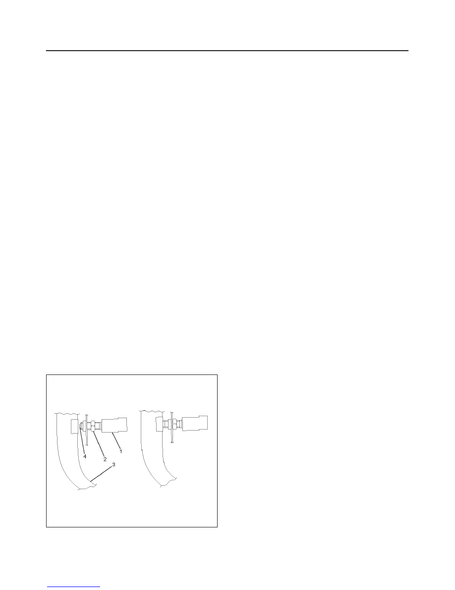
Adjustment
1. Check that the brake pedal (3) is fully returned by
pedal return spring.
2. Disconnect the switch connector.
3. Loosen the lock nut (2).
4. Rotate the brake switch (1) by hand until push rod
disappears from brake switch tip (4).
5. Return the brake switch by a half turn.
6. Tighten the lock nut.
7. Connect the switch connector.
310RS028
Нет комментариевНе стесняйтесь поделиться с нами вашим ценным мнением.
Текст