Isuzu Rodeo UE. Manual — part 650
9J1–37
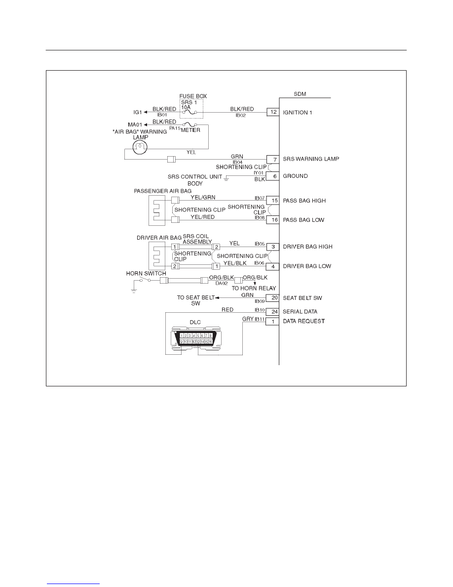
RESTRAINT CONTROL SYSTEM
2. This test verifies proper connection of the yellow
2–pin connector at the base of the steering column.
3. This test checks for proper contact and/or corrosion
of the yellow 2–pin connector at the base of the
steering column.
4. This test isolates the malfunction to one side of the
SRS coil assembly yellow 2–pin connector located
at the base of steering column.
5. This test determines whether the open is in the
wiring.
6. This test determines whether the malfunction is in
the SRS coil assembly or the driver air bag
assembly.
Diagnostic Aids:
An intermittent condition is likely to be caused by a poor
connection at the driver air bag assembly harness 2–pin
connector terminals “1” and “2” at the top of the steering
column, SRS coil assembly harness 2–pin connection
terminals “1” and “2”, SDM terminals “3” and “4”, or an
open in CKTs IB05–YEL and IB06–YEL/BLK.

RESTRAINT CONTROL SYSTEM
9J1–38
DTC 26 Driver Deployment Loop Open
Step
Action
Yes
No
1
Was the “SRS Diagnostic System Check” performed?
Go to Step 2
Go to the “SRS
Diagnostic
System Check.”
2
1. When measurements are requested in this chart use J–39200
DVM with correct terminal adapter from J–35616–A.
2. Use scan tool data list function, read and record the driver
differential voltage.
Is driver differential voltage more than 4.0 volts?
Go to Step 3
Go to Chart A.
3
1. Ignition switch “OFF.”
2. Make sure the SRS coil assembly yellow 2–pin connector
located at the base of steering column is seated properly.
Is the yellow 2–pin connector connected properly?
Go to Step 4
Seat driver air
bag assembly
2–pin connector.
Go to Step 8
4
1. Disconnect and inspect the SRS coil assembly yellow 2–pin
connector located base of steering column.
2. If OK, reconnect the SRS coil assembly yellow 2–pin
connector.
3. Ignition switch “ON”.
Is DTC 26 current?
Go to Step 5
Ignition switch
“OFF.”
Go to Step 8
5
1. Ignition switch “OFF.”
2. Disconnect SRS coil and passenger air bag assembly, yellow
2–pin connectors located at the base of steering column and
behind the glove box assembly.
3. Connect SRS driver / passenger load tool J–41433 and
appropriate adapter to SRS coil and passenger air bag
assembly harness connectors.
4. Ignition switch “ON.”
Is DTC 26 current?
Go to Step 6
Go to Step 7
6
1. Ignition switch “OFF.”
2. There has been an open circuit in the driver deployment loop.
Use the high resolution ohmmeter mode of the DVM while
checking CKTs IB05 YEL and IB06 YEL/BLK, and SDM
connector terminal “3” AND “4” to locate the root cause.
Was a fault found?
Replace SRS
harness.
Go to Step 8
Go to Chart A.
7
1. Ignition switch “OFF.”
2. Disconnect SRS driver / passenger load tool from SRS coil
assembly harness connector.
3. Connect SRS driver / passenger load tool J–41433 on steering
column.
4. Reconnect SRS coil assembly harness connector as the base
of steering column.
5. Ignition switch “ON.”
Is DTC 26 current?
Ignition switch
“OFF.”
Replace SRS coil
assembly, refer to
in this section
9J–3.
Go to Step 8
Ignition switch
“OFF.”
Replace driver air
bag assembly.
Go to Step 8
8
1. Reconnect all components, ensure all component are properly
mounted.
2. Clear diagnostic trouble codes.
Was this step finished?
Repeat the “SRS
Diagnostic
System Check.”
Go to Step 8
9J1–39
RESTRAINT CONTROL SYSTEM
DTC 51 Deployment Event Commanded
D09RW002
Circuit Description:
The SDM contains a sensing device which converts
vehicle velocity changes to an electrical signal. The
electrical signal generated is processed by the SDM and
then compared to a value stored in memory. When the
generated signal exceeds the stored value, the SDM will
cause current to flow through the air bag assembly
deploying the air bags and causing DTC 51 to set.
DTC Will Set When:
The SDM detects a frontal crash, up to 30 degrees off the
centerline of the vehicle, of sufficient force to warrant
deployment of the air bags.
Action Taken:
SDM turns “ON” the “AIR BAG” warning lamp records
“Crash Data”, and sets a diagnostic trouble code.
DTC Will Clear When:
The SDM is replaced.
DTC Chart Test Description:
Number(s) below refer to step number(s) on the
diagnostic chart:
2. If air bag assembly (s) has not deployed, DTC 51
may have falsely set.
3. If DTC 51 has set with no signs of frontal impact, the
diagnostic trouble code has falsely set.

RESTRAINT CONTROL SYSTEM
9J1–40
DTC 51 Deployment Event Commanded
WARNING: DURING SERVICE PROCEDURES. BE VERY CAREFUL WHEN HANDLING A SENSING AND
DIAGNOSTIC MODULE (SDM). NEVER STRIKE OR JAR THE SDM. NEVER POWER UP THE SRS WHEN THE
SDM IS NOT RIGIDLY ATTACHED TO THE VEHICLE. ALL SDM AND MOUNTING BRACKET FASTENERS MUST
BE CAREFULLY TORQUED AND THE ARROW MUST BE POINTING TOWARD THE FRONT OF THE VEHICLE
TO ENSURE PROPER OPERATION OF THE SRS. THE SDM COULD BE ACTIVATED WHEN POWERED WHILE
NOT RIGIDLY ATTACHED TO THE VEHICLE WHICH COULD CAUSE DEPLOYMENT AND RESULT IN
PERSONAL INJURY.
Step
Action
Yes
No
1
Was the “SRS Diagnostic System Check” performed?
Go to Step 2
Go to the “SRS
Diagnostic
System Check.”
2
Ignition switch “OFF.”
Have air bag assemblies deployed?
Replace
components and
perform
inspections as
directed in
“repairs and
inspections
required after an
accident” in this
section.
Clear diagnostic
trouble codes.
Repeat the “SRS
Diagnostic
System Check.”
Go to Step 3
3
Inspect front of vehicle and undercarriage for signs of impact.
Were signs of impact found?
Replace
components and
perform
inspections as
directed in
“repairs and
inspections
required after an
accident” in this
section.
Clear diagnostic
trouble codes.
Repeat the “SRS
Diagnostic
System Check.”
Ignition switch
“OFF.”
Replace SDM.
Reconnect all
SRS system
components,
ensure all
components are
properly
mounted.Repeat
the “SRS
Diagnostic
System Check.”
Нет комментариевНе стесняйтесь поделиться с нами вашим ценным мнением.
Текст