Isuzu Rodeo UE. Manual — part 651
9J1–41
RESTRAINT CONTROL SYSTEM
DTC 53 Deployment Commanded With Deployment Loop Fault Or Energy
Reserves Out Of Range
D09RW002
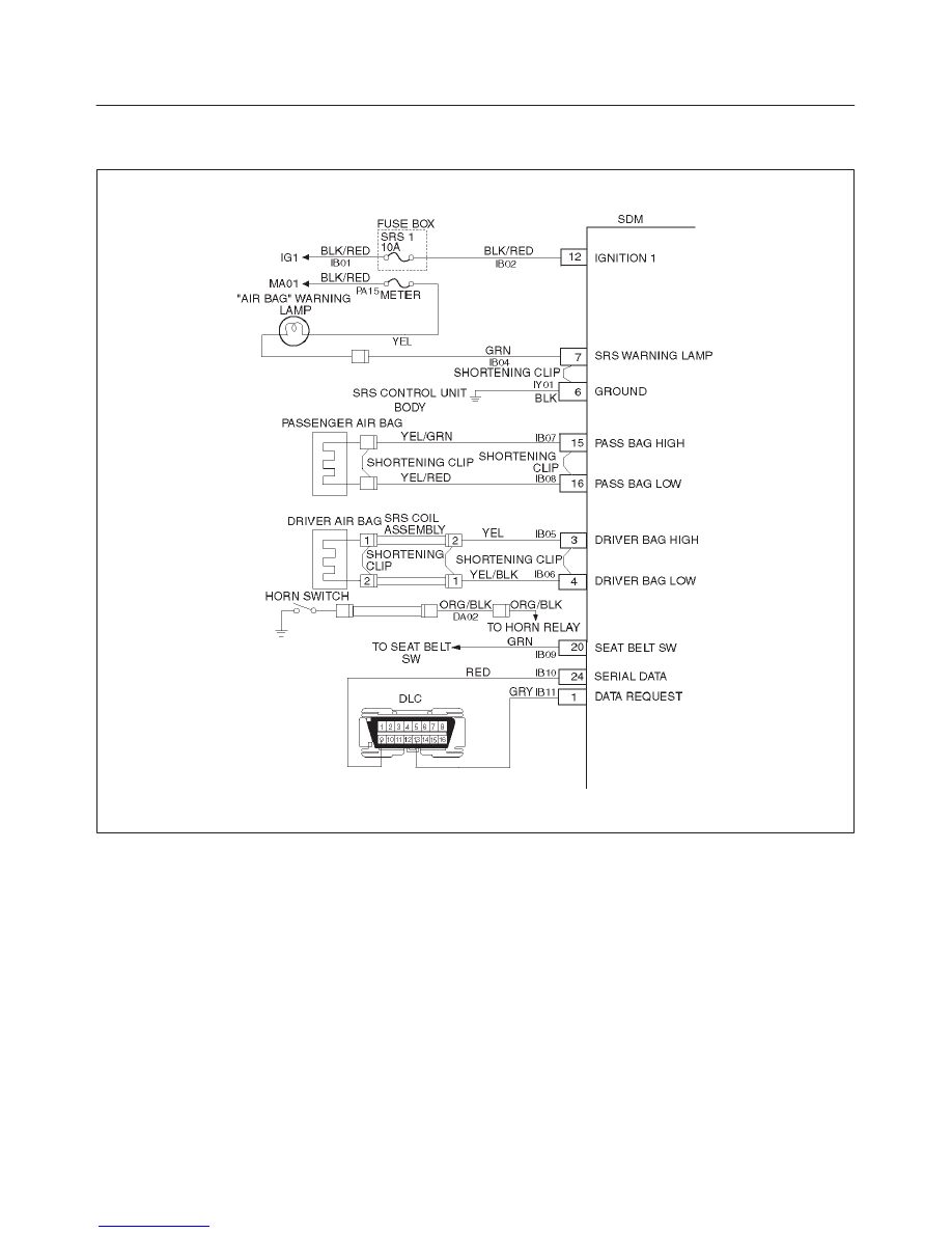
Circuit Description:
The SDM contains a sensing drive which converts vehicle
velocity changes to an electrical signal. The electrical
signal generated is processed by the SDM and then
compared to a value stored in memory. When the
generated signal exceeds the stored value, the SDM will
cause current to flow through the air bag assembly
deploying the air bags. DTC 53 is set accompanying with
DTC 51 when a deployment occurs while an air bag
assembly circuit fault is present that could possible result
in a no deployment situation in one or both air bag
assemblies.
DTC Will Set When:
The SDM detects a frontal crash, up to 30 degrees off the
centerline of the vehicle, of sufficient force to warrant
deployment of the air bags and an inflator circuit fault is
present.
Action Taken:
SDM turns “ON” the “AIR BAG” warning lamp records
“Crash Data”, and sets a diagnostic trouble code.
DTC Will Clear When:
The SDM is replaced. If DTC 53 is set, one or more DTCs
will be set in addition to DTC 53. Malfunction(s) setting
DTC(s) (other than DTC 71) must be repaired so that
DTC(s) will not be set when a new SDM is installed.
DTC Chart Test Description:
Number(s) below refer to step number(s) on the
diagnostic chart:
2. If air bag assembly has not deployed, DTC 53 may
have falsely set.
3. If DTC 53 has set with no signs of frontal impact, the
diagnostic trouble code has falsely set.

RESTRAINT CONTROL SYSTEM
9J1–42
DTC 53 Deployment Commanded With Deployment Loop Fault Or Energy Reserves Out
Of Range
WARNING: DURING SERVICE PROCEDURES. BE VERY CAREFUL WHEN HANDLING A SENSING AND
DIAGNOSTIC MODULE (SDM). NEVER STRIKE OR JAR THE SDM. NEVER POWER UP THE SRS WHEN THE
SDM IS NOT RIGIDLY ATTACHED TO THE VEHICLE. ALL SDM AND MOUNTING BRACKET FASTENERS MUST
BE CAREFULLY TORQUED AND THE ARROW MUST BE POINTING TOWARD THE FRONT OF THE VEHICLE
TO ENSURE PROPER OPERATION OF THE SRS. THE SDM COULD BE ACTIVATED WHEN POWERED WHILE
NOT RIGIDLY ATTACHED TO THE VEHICLE WHICH COULD CAUSE DEPLOYMENT AND RESULT IN
PERSONAL INJURY.
Step
Action
Yes
No
1
Was the “SRS Diagnostic System Check” performed?
Go to Step 2
Go to the “SRS
Diagnostic
System Check.”
2
Ignition switch “OFF.”
Have air bag assemblies deployed?
Replace
components and
perform
inspections as
directed in
“repairs and
inspections
required after an
accident” in this
section.
Clear diagnostic
trouble codes.
Repeat the “SRS
Diagnostic
System Check.”
Go to Step 3
3
Inspect front of vehicle and undercarriage for signs of impact.
Were signs of impact found?
Replace
components and
perform
inspections as
directed in
“repairs and
inspections
required after an
accident” in this
section.
Clear diagnostic
trouble codes.
Repeat the “SRS
Diagnostic
System Check.”
Ignition switch
“OFF.”
Replace SDM.
Reconnect all
SRS system
components,
ensure all
components are
properly
mounted.
Repeat the “SRS
Diagnostic
System Check.”

9J1–43
RESTRAINT CONTROL SYSTEM
DTC 61 Warning Lamp Circuit Failure
D09RW002
Circuit Description:
When the ignition switch is turned “ON”, battery voltage is
applied to the “AIR BAG” warning lamp and to the “ignition
1” input terminal “12”. The SDM responds by flashing the
“AIR BAG” warning lamp seven times. The SDM
monitors the lamp driver output by comparing the output
state at “SRS warning lamp” terminal “7” to the
microprocessor commanded state. When “ignition 1” is in
the specified value, and the output state Does not match
the commanded state of the lamp driver for 500
milliseconds, DTC 61 is set.
DTC Will Set When:
“Ignition 1” voltage is in the specified value and the output
state at the “SRS warning lamp” terminal does not match
the commanded state of the lamp driver for 500
milliseconds. This test is run every 100 milliseconds
during “Continuous Monitoring” tests and once per each
ignition cycle at the beginning.
Action Taken:
SDM attempts to turn “ON” the “AIR BAG” warning lamp
and sets a diagnostic trouble code.
DTC Will Clear When:
The ignition switch is turned “OFF.”
Diagnostic Aids:
Refer to Charts B and C to diagnose warning lamp circuit
malfunctions.

RESTRAINT CONTROL SYSTEM
9J1–44
DTC 61 Warning Lamp Circuit Failure
Step
Action
Yes
No
1
Was the “SRS Diagnostic System Check” performed?
Go to Step 2
Go to the “SRS
Diagnostic
System Check.”
2
1. Malfunctions within the “AIR BAG” warning lamp circuitry will
set this diagnostic trouble code.
2. These malfunctions are addressed in the “SRS Diagnostic
System Check” via Chart B and Chart C.
3. Failure to properly perform the “SRS Diagnostic System
Check” may result in misdiagnosis.
4. Ignition switch “ON.”
5. Clear SRS diagnostic trouble codes.
Is DTC 61 SET?
Ignition switch
“OFF.”
Go to Chart A.
Repeat the “SRS
Diagnostic
System Check.”
Нет комментариевНе стесняйтесь поделиться с нами вашим ценным мнением.
Текст