Isuzu Rodeo UE. Manual — part 254
6E1–387
RODEO X22SE 2.2L ENGINE DRIVEABILITY AND EMISSION
4. Remove the sensor from intake air duct by using a
rocking motion while pulling the sensor.
0018
Installation Procedure
1. Install the IAT sensor into intake air duct. Make sure
the sensoris pushed all the way into the intake air
duct.
2. Connect electrical connector.
3. Connect the negative battery cable.
014RX011
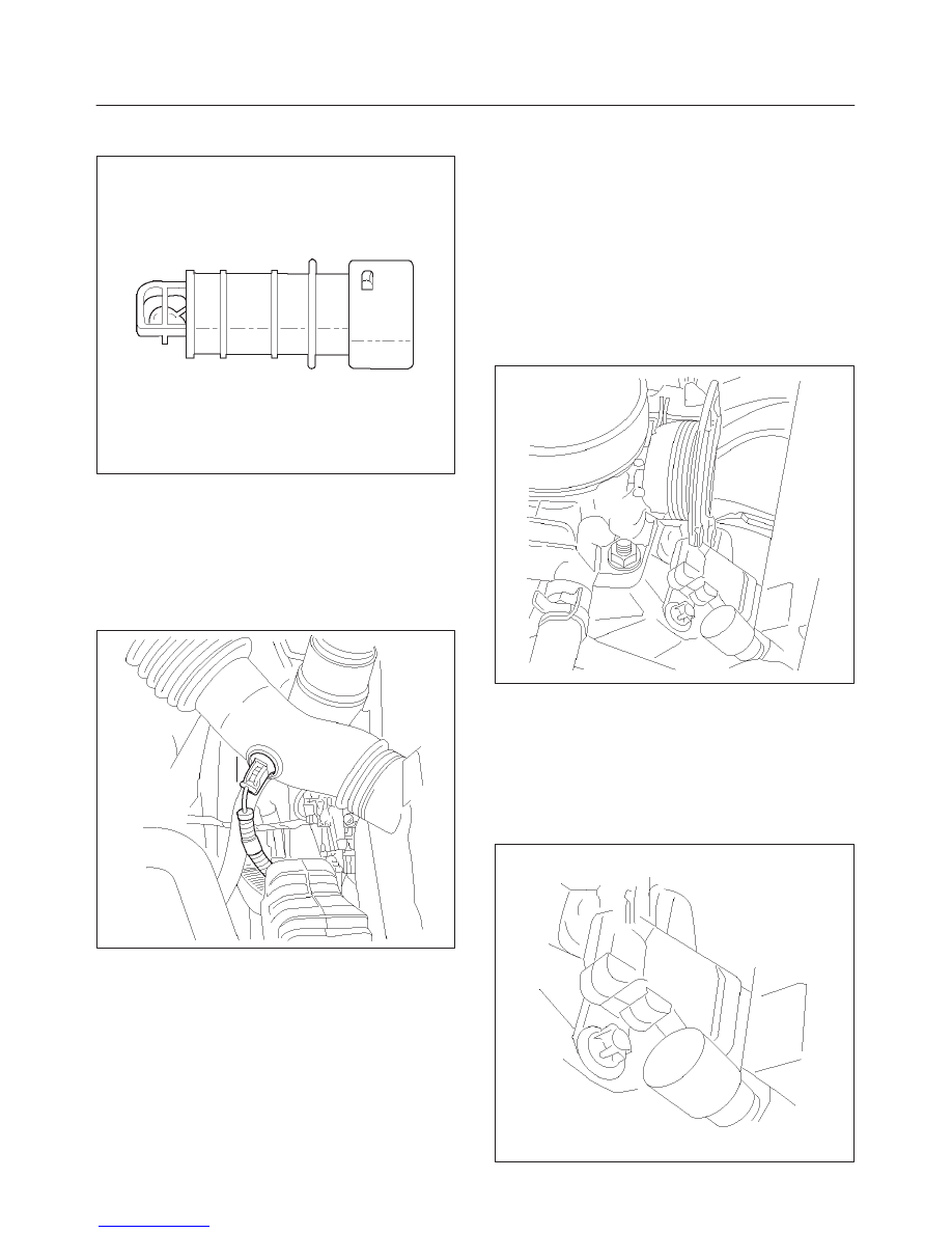
Manifold Absolute Pressure
(MAP) Sensor
Removal Procedure
1. Disconnect the negative battery cable.
2. Disconnect the electrical connector from the sensor.
(The MAP sensoris located on the intake manifold
behind throttle body.)
3. Remove a mounting bolt securing the sensor to the
manifold.
4. Remove the sensor from the intake manifold using
rocking motion while pulling the sensor.
014RX012
Installation Procedure
1. Push MAP sensor into the manifold. Make sure the
sensor is pushed always into its position.
2. Install a mounting bolts and tighten.
3. Connect electrical connector.
4. Connect the negative battery cable.
014RX013
6E1–388
RODEO X22SE 2.2L ENGINE DRIVEABILITY AND EMISSION
Malfunction Indicator Lamp
(MIL)
Malfunction Indicator Lamp (MIL)
Refer to Instrument Panel Removal Procedure.
Powertrain Control Module
(PCM)
Electrostatic Discharge (ESD)
Damage
Electronic components used in the control system are
often designed to carry very low voltage. Electronic
components are susceptible to damage caused by
electrostatic discharge. Less than 100 volts of static
electricity can cause damage to same electronic
components. By comparison, it takes as much as 4000
volts for a person to even feel the zap of a static
discharge. There are several way for a person to become
statically charged. The most common methods of
charging are by friction and by induction. An example of
charging by friction is a person sliding across a car seat.
Charging by induction occurs when a person with well
insulated shoes stands near a highly charged object and
momentarily touches ground. Charge of the same polarity
are drained off leaving the person highly charged with
opposite polarity. Static charge can cause damage,
therefore, it is important to use care when handling and
testing electronic components.
NOTE: To prevent possible Electrostatic Discharge
damage, follow these guidelines:
f
Do not touch the control module connector pins or
soldered components on the control module circuit
board.
f
Do not open the replacement part package until the
part is ready to be installed.
f
Before removing the parts from the package, ground
the package to a known good ground on the vehicle.
f
If the parts been handled while sliding across the
seat, or while sitting from standing position, or walking
a distance, touch a known good ground before
installing the parts.
014RX002
NOTE: To prevent internal PCM damage, the ignition
must be OFF position in order to disconnect or reconnect
power to the PCM (for example: battery cable. pig tail,
PCM fuse, jumper cable, etc.).
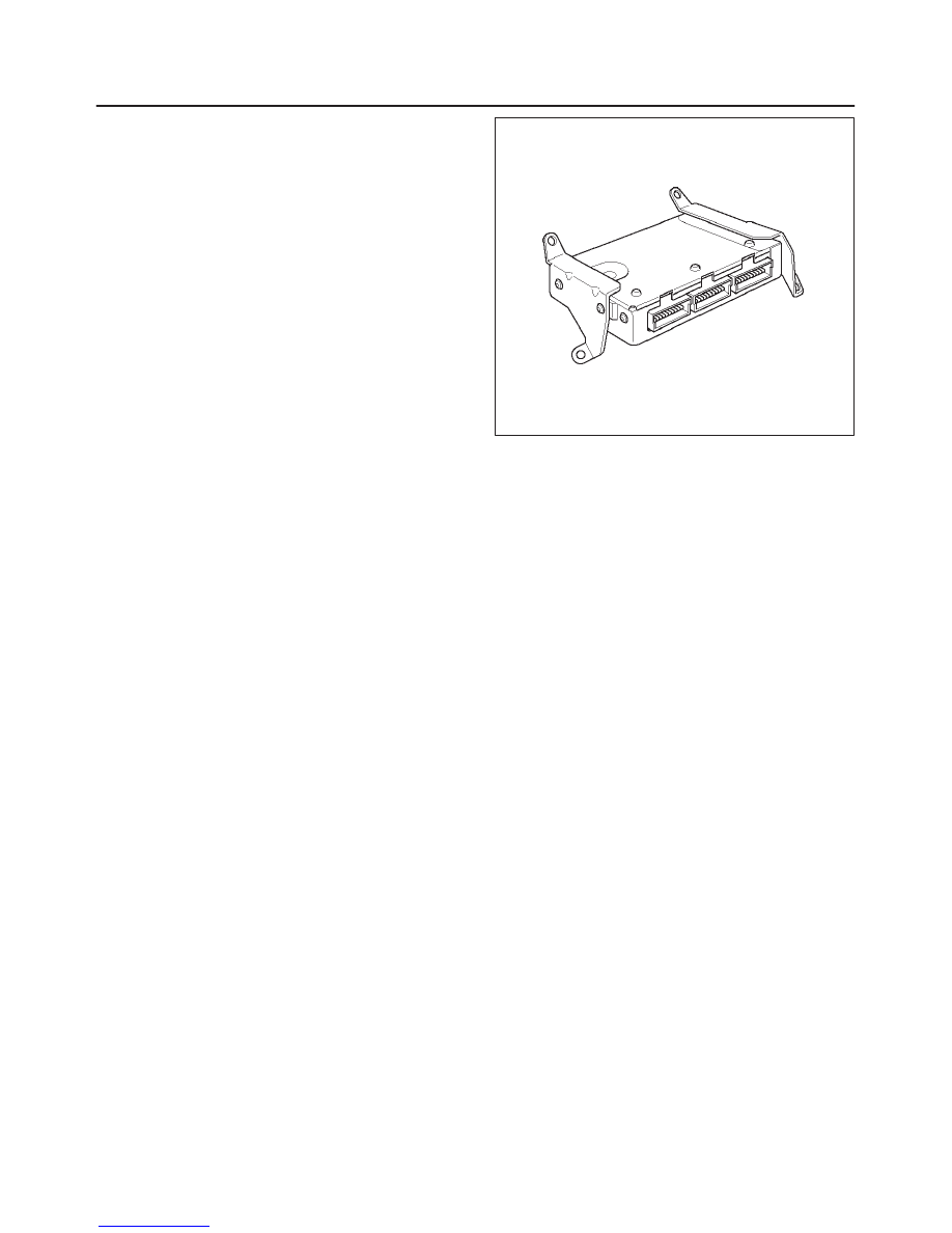
IMPORTANT:
When replacing the production PCM
with a service PCM, it is important to transfer the
broadcast code and production PCM number to the
service PCM label. This will allow positive identification of
PCM parts throughout the service life of the vehicle. Do
not record this information on PCM metal cover.
IMPORTANT:
The ignition should always be in the OFF
position in order to install or remove the PCM connectors.
Service of the PCM should normally consist of either
replacement of the PCM or EEPROM reprogramming. If
the diagnostic procedure call for the PCM to be replaced,
the replacement PCM should be checked first to ensure it
has the correct part number. If it is, remove the faulty PCM
and install the new service PCM. The service PCM
EEPROM will need to be programmed. Additionally, after
programming, the CKP Sensor Tooth Error Correction
(TEC) Learn procedure will need to be performed.
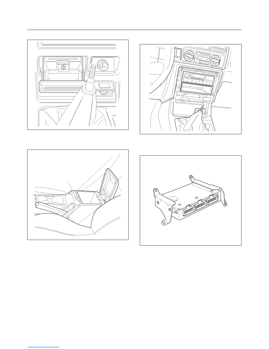
Removal Procedure
1. Disconnect the negative battery cable.
2. Block the wheels.
3. Remove ashtray inner.
6E1–389
RODEO X22SE 2.2L ENGINE DRIVEABILITY AND EMISSION
4. Remove a screw located behind ashtray.
014RX014
5. Pull out Face trim of console.
6. Remove two screws located inside of center console
storage box and pull up rear part of center console.
014RX015
7. Unscrew the shift knob.
8. Remove four screw holding front part of the console
and pull the console up.
9. Disconnect the red, white and blue electrical
connector at the PCM.
014RX016
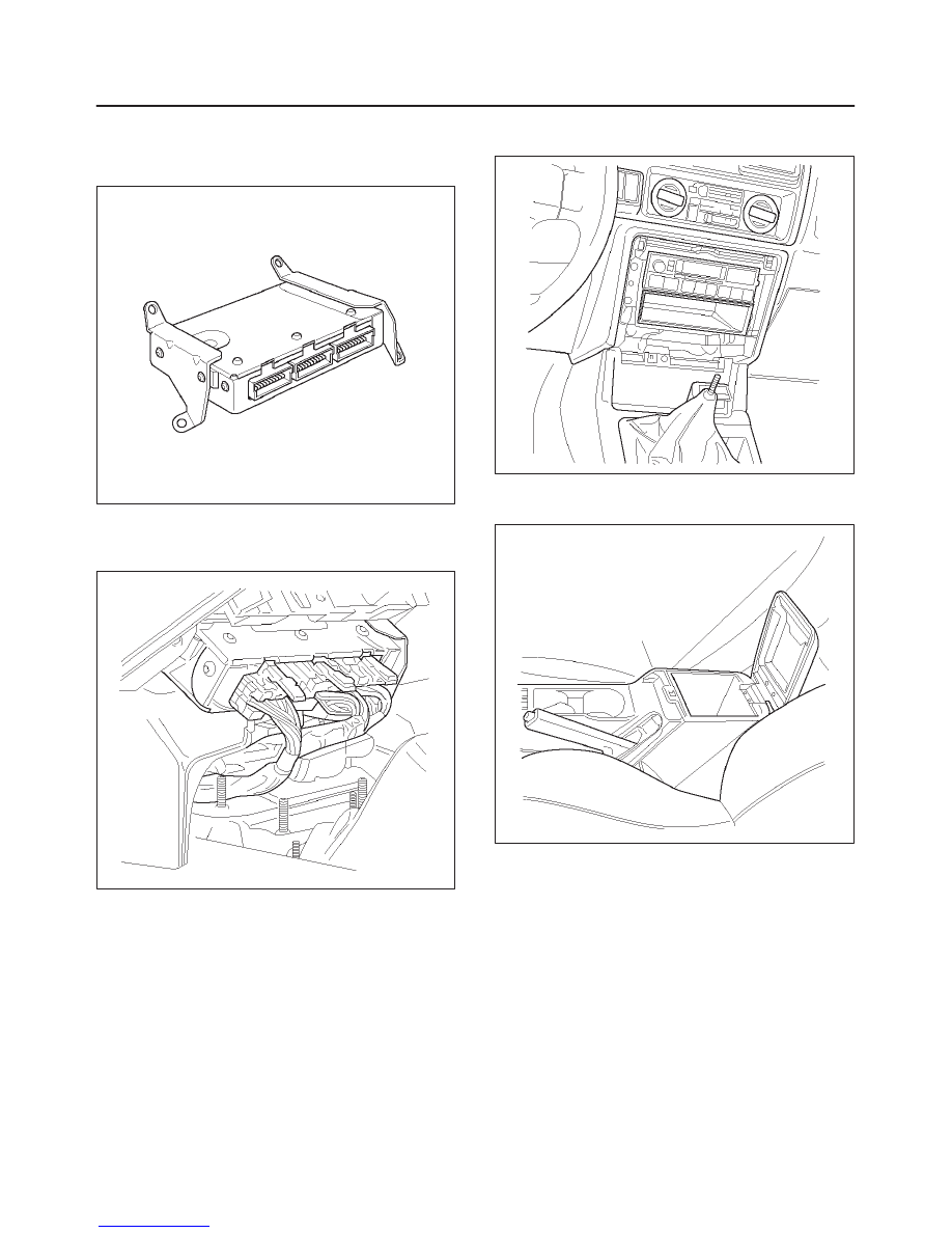
10. Remove two nuts in the front of PCM.
11. Remove two nuts in the rear of PCM.
12. Pull the PCM out from dashboard.
014RX002
6E1–390
RODEO X22SE 2.2L ENGINE DRIVEABILITY AND EMISSION
Installation Procedure
1. Place PCM into its position and secure by four
mounting screws.
014RX002
2. Connect all three connectors to PCM. All connectors
are color keyed. Same color male and female
connectors join together.
014RX017
3. Install the front center console and secure by four
retaining screws.
014RX016
4. Install the rear center console and secure it by two
retaining screw into storage box.
014RX015
5. Snap face plate into its position and secure it by a
screw.
6. Insert ashtray inner.
7. Insert the shift knob.
8. Connect the negative battery cable.
Нет комментариевНе стесняйтесь поделиться с нами вашим ценным мнением.
Текст