Isuzu Rodeo UE. Manual — part 110
5C–1
POWER–ASSISTED BRAKE SYSTEM
RODEO
BRAKES
POWER-ASSISTED BRAKE SYSTEM
CONTENTS
Service Precaution
5C–2
. . . . . . . . . . . . . . . . . . . . . .
General Description
5C–2
. . . . . . . . . . . . . . . . . . . . .
Diagnosis
5C–6
. . . . . . . . . . . . . . . . . . . . . . . . . . . . . .
General Diagnosis
5C–7
. . . . . . . . . . . . . . . . . . . . . . .
Hydraulic Brakes
5C–10
. . . . . . . . . . . . . . . . . . . . . . . .
Filling Master Cylinder Reservoir
5C–10
. . . . . . . .
Deterioration of Brake Fluid
5C–10
. . . . . . . . . . . . .
Leakage of Brake Fluid
5C–10
. . . . . . . . . . . . . . . . .
Bleeding Brake Hydraulic System
5C–10
. . . . . . . .
Flushing Brake Hydraulic System
5C–11
. . . . . . . .
Brake Pipes and Hoses
5C–11
. . . . . . . . . . . . . . . .
Brake Hose Inspection
5C–11
. . . . . . . . . . . . . . . . .
Front Caliper Brake Hose
5C–12
. . . . . . . . . . . . . . . .
Front Caliper Brake Hose and Associated
Parts
5C–12
. . . . . . . . . . . . . . . . . . . . . . . . . . . . . . . .
Removal
5C–12
. . . . . . . . . . . . . . . . . . . . . . . . . . . . .
Installation
5C–12
. . . . . . . . . . . . . . . . . . . . . . . . . . . .
Rear Axle Brake Hose
5C–13
. . . . . . . . . . . . . . . . . . .
Rear Axle Brake Hose and Associated
Parts
5C–13
. . . . . . . . . . . . . . . . . . . . . . . . . . . . . . . .
Removal
5C–13
. . . . . . . . . . . . . . . . . . . . . . . . . . . . .
Installation
5C–13
. . . . . . . . . . . . . . . . . . . . . . . . . . . .
Brake Pipe
5C–14
. . . . . . . . . . . . . . . . . . . . . . . . . . . . .
Removal
5C–14
. . . . . . . . . . . . . . . . . . . . . . . . . . . . .
Installation
5C–14
. . . . . . . . . . . . . . . . . . . . . . . . . . . .
P & B (Proportioning and Bypass) Valve
5C–15
. . . .
Removal
5C–15
. . . . . . . . . . . . . . . . . . . . . . . . . . . . .
Installation
5C–15
. . . . . . . . . . . . . . . . . . . . . . . . . . . .
Main Data and Specifications
5C–16
. . . . . . . . . . . . .
Brake Pedal
5C–17
. . . . . . . . . . . . . . . . . . . . . . . . . . . .
Checking Pedal Height
5C–17
. . . . . . . . . . . . . . . . .
Checking Pedal Travel
5C–17
. . . . . . . . . . . . . . . . .
Brake Pedal and Associated Parts
5C–18
. . . . . . .
Removal
5C–18
. . . . . . . . . . . . . . . . . . . . . . . . . . . . .
Installation
5C–18
. . . . . . . . . . . . . . . . . . . . . . . . . . . .
Stoplight Switch
5C–19
. . . . . . . . . . . . . . . . . . . . . . . . .
Parts Location
5C–19
. . . . . . . . . . . . . . . . . . . . . . . .
Removal
5C–19
. . . . . . . . . . . . . . . . . . . . . . . . . . . . .
Installation
5C–19
. . . . . . . . . . . . . . . . . . . . . . . . . . . .
Main Data and Specifications
5C–20
. . . . . . . . . . . . .
Fluid Reservoir Tank
5C–21
. . . . . . . . . . . . . . . . . . . . .
Fluid Reservoir Tank and Associated Parts
5C–21
Removal
5C–21
. . . . . . . . . . . . . . . . . . . . . . . . . . . . .
Installation
5C–21
. . . . . . . . . . . . . . . . . . . . . . . . . . . .
Master Cylinder Assembly
5C–22
. . . . . . . . . . . . . . . .
Master Cylinder Assembly and Associated
Parts
5C–22
. . . . . . . . . . . . . . . . . . . . . . . . . . . . . . . .
Removal
5C–22
. . . . . . . . . . . . . . . . . . . . . . . . . . . . .
Inspection and Repair
5C–22
. . . . . . . . . . . . . . . . . .
Installation
5C–23
. . . . . . . . . . . . . . . . . . . . . . . . . . . .
Main Data and Specifications
5C–24
. . . . . . . . . . .
Special Tools
5C–24
. . . . . . . . . . . . . . . . . . . . . . . . . .
Vacuum Booster Assembly
5C–25
. . . . . . . . . . . . . . .
Vacuum Booster Assembly and Associated
Parts
5C–25
. . . . . . . . . . . . . . . . . . . . . . . . . . . . . . . .
Removal
5C–25
. . . . . . . . . . . . . . . . . . . . . . . . . . . . .
Inspection and Repair
5C–25
. . . . . . . . . . . . . . . . . .
Installation
5C–26
. . . . . . . . . . . . . . . . . . . . . . . . . . . .
Exterior Components
5C–28
. . . . . . . . . . . . . . . . . . . .
Exterior Components and Associated Parts
5C–28
Removal
5C–28
. . . . . . . . . . . . . . . . . . . . . . . . . . . . .
Inspection and Repair
5C–29
. . . . . . . . . . . . . . . . . .
Installation
5C–29
. . . . . . . . . . . . . . . . . . . . . . . . . . . .
Vacuum Booster Overhaul
5C–29
. . . . . . . . . . . . . . . .
Vacuum Booster
5C–29
. . . . . . . . . . . . . . . . . . . . . . .
Main Data and Specifications
5C–30
. . . . . . . . . . . . .
Special Tools
5C–31
. . . . . . . . . . . . . . . . . . . . . . . . . . .
Front Disc Brake Pads
5C–32
. . . . . . . . . . . . . . . . . . .
Front Disc Brake Pads Inspection
5C–32
. . . . . . . .
Front Disc Brake Pads and Associated
Parts
5C–32
. . . . . . . . . . . . . . . . . . . . . . . . . . . . . . . .
Removal
5C–33
. . . . . . . . . . . . . . . . . . . . . . . . . . . . .
Installation
5C–33
. . . . . . . . . . . . . . . . . . . . . . . . . . . .
Front Disc Brake Rotor
5C–35
. . . . . . . . . . . . . . . . . . .
Inspection
5C–35
. . . . . . . . . . . . . . . . . . . . . . . . . . . .
Replacing Brake Rotors
5C–35
. . . . . . . . . . . . . . . .
Refinishing Brake Rotors
5C–35
. . . . . . . . . . . . . . .
Front Disc Brake Caliper Assembly
5C–36
. . . . . . . .
Front Disc Brake Caliper Assembly and
Associated Parts
5C–36
. . . . . . . . . . . . . . . . . . . . . .
Removal
5C–37
. . . . . . . . . . . . . . . . . . . . . . . . . . . . .
Installation
5C–37
. . . . . . . . . . . . . . . . . . . . . . . . . . . .
Front Disc Brake Caliper
5C–39
. . . . . . . . . . . . . . . . .
Front Disc Brake Caliper Disassembled
View
5C–39
. . . . . . . . . . . . . . . . . . . . . . . . . . . . . . . .
Disassembly
5C–39
. . . . . . . . . . . . . . . . . . . . . . . . . .
Inspection and Repair
5C–40
. . . . . . . . . . . . . . . . . .
Reassembly
5C–40
. . . . . . . . . . . . . . . . . . . . . . . . . .
Main Data and Specifications
5C–42
. . . . . . . . . . .
5C–2
POWER–ASSISTED BRAKE SYSTEM
Rear Disc Brake Pads (4
×
4 Model)
5C–43
. . . . . . . .
Brake Pads Inspection
5C–43
. . . . . . . . . . . . . . . . .
Brake Pads and Associated Parts
5C–43
. . . . . . .
Removal
5C–44
. . . . . . . . . . . . . . . . . . . . . . . . . . . . .
Installation
5C–44
. . . . . . . . . . . . . . . . . . . . . . . . . . . .
Rear Disc Brake Rotor (4
×
4 Model)
5C–46
. . . . . . . .
Inspection
5C–46
. . . . . . . . . . . . . . . . . . . . . . . . . . . .
Replacing Brake Rotors
5C–46
. . . . . . . . . . . . . . . .
Refinishing Brake Rotors
5C–46
. . . . . . . . . . . . . . .
Rear Drum (In Disc) Inside Diameter Check
5C–47
Rear Disc Brake Caliper Assembly
(4
×
4 Model)
5C–48
. . . . . . . . . . . . . . . . . . . . . . . . . . . .
Rear Disc Brake Caliper Assembly and
Associated Parts
5C–48
. . . . . . . . . . . . . . . . . . . . . .
Removal
5C–48
. . . . . . . . . . . . . . . . . . . . . . . . . . . . .
Installation
5C–49
. . . . . . . . . . . . . . . . . . . . . . . . . . . .
Rear Disc Brake Caliper (4
×
4 Model)
5C–50
. . . . . .
Rear Disc Brake Caliper Disassembled
View
5C–50
. . . . . . . . . . . . . . . . . . . . . . . . . . . . . . . .
Disassembly
5C–51
. . . . . . . . . . . . . . . . . . . . . . . . . .
Inspection and Repair
5C–51
. . . . . . . . . . . . . . . . . .
Reassembly
5C–51
. . . . . . . . . . . . . . . . . . . . . . . . . .
Main Data and Specifications (4
×
4 Model)
5C–53
Brake Lining
5C–54
. . . . . . . . . . . . . . . . . . . . . . . . . . . .
Brake Lining and Associated Parts
5C–54
. . . . . . .
Removal
5C–54
. . . . . . . . . . . . . . . . . . . . . . . . . . . . .
Brake Lining Inspection
5C–55
. . . . . . . . . . . . . . . .
Installation
5C–55
. . . . . . . . . . . . . . . . . . . . . . . . . . . .
Drum Brake Adjustment (4
×
2 Model)
5C–56
. . . . .
Servicing The Brake Drum
5C–56
. . . . . . . . . . . . . .
Wheel Cylinder Assembly (4
×
2 Model)
5C–57
. . . . .
Wheel Cylinder Assembly and Associated
Parts
5C–57
. . . . . . . . . . . . . . . . . . . . . . . . . . . . . . . .
Removal
5C–57
. . . . . . . . . . . . . . . . . . . . . . . . . . . . .
Installation
5C–57
. . . . . . . . . . . . . . . . . . . . . . . . . . . .
Disassembled View
5C–58
. . . . . . . . . . . . . . . . . . . .
Disassembly
5C–58
. . . . . . . . . . . . . . . . . . . . . . . . . .
Inspection and Repair
5C–58
. . . . . . . . . . . . . . . . . .
Reassembly
5C–58
. . . . . . . . . . . . . . . . . . . . . . . . . .
Main Data and Specifications
5C–60
. . . . . . . . . . .
Service Precaution
WARNING: THIS VEHICLE HAS A SUPPLEMENTAL
RESTRAINT SYSTEM (SRS). REFER TO THE SRS
COMPONENT AND WIRING LOCATION VIEW IN
ORDER TO DETERMINE WHETHER YOU ARE
PERFORMING SERVICE ON OR NEAR THE SRS
COMPONENTS OR THE SRS WIRING. WHEN YOU
ARE PERFORMING SERVICE ON OR NEAR THE SRS
COMPONENTS OR THE SRS WIRING, REFER TO
THE SRS SERVICE INFORMATION. FAILURE TO
FOLLOW WARNINGS COULD RESULT IN POSSIBLE
AIR BAG DEPLOYMENT, PERSONAL INJURY, OR
OTHERWISE UNNEEDED SRS SYSTEM REPAIRS.
CAUTION: Always use the correct fastener in the
proper location. When you replace a fastener, use
ONLY the exact part number for that application.
ISUZU will call out those fasteners that require a
replacement after removal. ISUZU will also call out
the fasteners that require thread lockers or thread
sealant. UNLESS OTHERWISE SPECIFIED, do not
use supplemental coatings (Paints, greases, or other
corrosion inhibitors) on threaded fasteners or
fastener joint interfaces. Generally, such coatings
adversely affect the fastener torque and the joint
clamping force, and may damage the fastener. When
you install fasteners, use the correct tightening
sequence and specifications. Following these
instructions can help you avoid damage to parts and
systems.
General Description
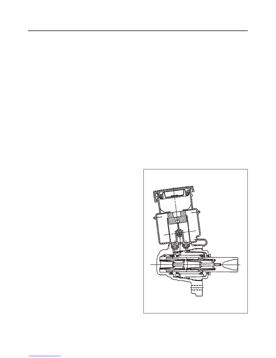
Master Cylinder Assembly
330RS001
5C–3
POWER–ASSISTED BRAKE SYSTEM
The master cylinder contains two pistons that supply the
hydraulic pressure for a dual–circuit braking system. The
primary piston provides the fluid pressure to the front
brakes, while the secondary piston provides the fluid
pressure to the rear brakes. If the pressure is lost from
either system, the remaining system will function to stop
the vehicle.
CAUTION:
1. The master cylinder is not repairable. If found
defective, it must be replaced as a complete
assembly.
2. If any hydraulic component is removed or
disconnected, it may be necessary to bleed all or
part of the brake system. (Refer to “Bleeding
Brake Hydraulic System” in this section.)
3. The torque values specified are for dry,
unlubricated fasteners.
4. Perform service operations on a clean bench free
from all mineral oil materials.
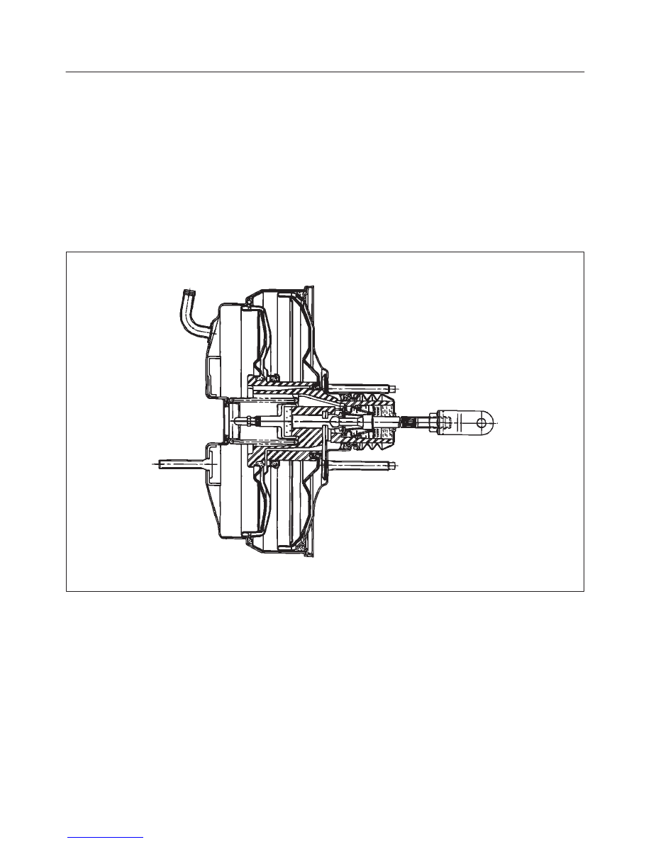
Brake Booster
331RS001
This booster is a tandem vacuum unit with a diaphragm
effective diameter 205mm + 230mm. In normal operating
mode, with the service brakes in the released position,
the tandem vacuum booster operates with vacuum on
both sides of its diaphragms. When the brakes are
applied, air at atmospheric pressure is admitted to one
side of each diaphragm to provide the power assist.
When the service brake is released, the atmospheric air is
shut off from the one side of each diaphragm. The air is
then drawn from the booster through the vacuum check
valve to the vacuum source.
CAUTION:
1. If any hydraulic component is removed or
disconnected, it may be necessary to bleed all or
part of the brake system.
2. The torque values specified are for dry,
unlubricated fasteners.
3. The vacuum booster is not repairable and must be
replaced as complete assembly.
5C–4
POWER–ASSISTED BRAKE SYSTEM
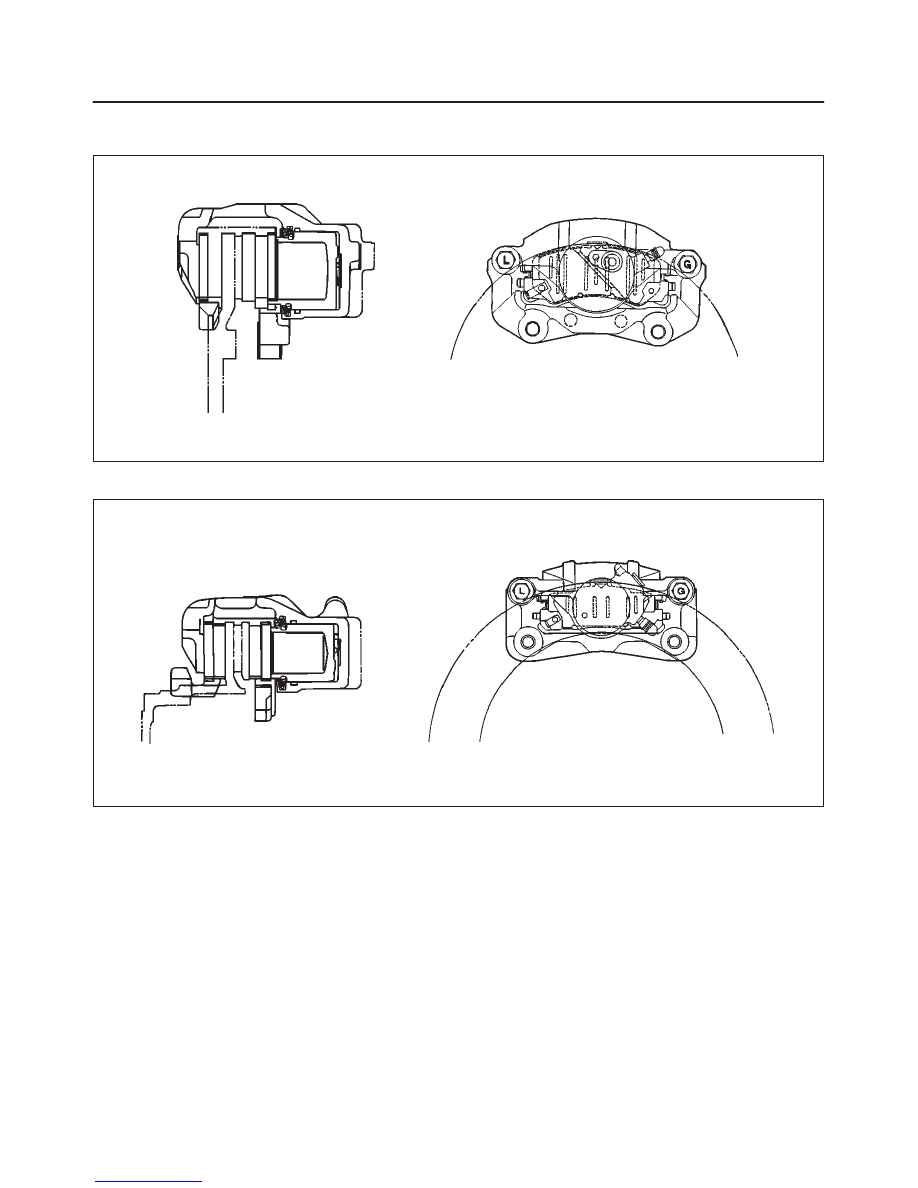
Disc Brake
Front Disc Brake
A05RW001
Rear Disc Brake (4
×
4 Model)
A05RW002
The disc brake assembly consists of a caliper, piston,
rotor, pad assembly and support bracket. The caliper
assembly has a single bore and is mounted to the support
bracket with two mounting bolts. The support bracket
allows the caliper to move laterally against the rotor. The
caliper is a one–piece casting with the inboard side
containing the piston bore. A square cut rubber seal is
located in a groove in the piston bore which provides the
hydraulic seal between the piston and the cylinder wall.
NOTE:
1. Replace all components included in repair kits used to
service this caliper.
2. Lubricate rubber parts with clean brake fluid to ease
assembly.
3. If any hydraulic component is removed or
disconnected, it may be necessary to bleed all or part
of the brake system.
4. Replace pads in axle sets only.
5. The torque values specified are for dry, unlubricated
fasteners.
6. Perform the service operation on a clean bench free
from all mineral oil materials.
Operation
Hydraulic pressure, created by applying the brake pedal,
is converted by the caliper to a stopping force. This force
acts equally against the piston and the bottom of the
caliper bore to move the piston outward and to move
(slide) the caliper inward resulting in a clamping action on
the rotor. This clamping action forces the linings against
the rotor, creating friction to stop the vehicle.
Нет комментариевНе стесняйтесь поделиться с нами вашим ценным мнением.
Текст