Isuzu Rodeo UE. Manual — part 108

5A–55
BRAKE CONTROL SYSTEM
Chart C-1-2 FR Sensor Output Inspection Procedure
Step
Action
Yes
No
1
1. Turn the key off.
2. Disconnect coil integrated module connector.
3. Jack up the vehicle with all four wheels off the ground.
Measure the AC voltage between coil integrated module
connector terminals while turning FR wheel at a speed of 1
RPS:
Is the check between coil integrated module connector (C-4)
terminals 3 and 11 than under 200 mV?
Go to Step 2
OK.
Go to Step 3
2
1. Disconnect the wheel speed sensor.
2. Measure resistance between the wheel speed sensor
connector terminals 1 and 2.
Is the check between connector (C-33) terminals 1 and 2 within
2.0k - 2.8k ohms?
Connector is
faulty, or open or
short circuit of
harness between
wheel speed
sensor connector
and coil
integrated
module.
Inspect and
correct the
connector or
harness.
Go to Step 3
Wheel speed
sensor is faulty.
Replace the
wheel speed
sensor.
Go to Step 3
3
Reconnect all components, ensure all components are properly
mounted.
Was this step finished?
Repeat the “Basic
diagnostic flow
chart”
Go to Step 3
Chart C-1-3 Rear Sensor Output Inspection Procedure
Step
Action
Yes
No
1
1. Turn the key off.
2. Disconnect coil integrated module connector.
3. Jack up the vehicle with all four wheels off the ground measure
the AC voltage between coil integrated module connector
terminals while turning Rear wheel at a speed of 1 RPS:
Is the check between coil integrated module connector (C-4)
terminals 4 and 12 than under 200 mV?
Go to Step 2
OK.
Go to Step 3
2
1. Disconnect the wheel speed sensor.
2. Measure resistance between the wheel speed sensor
connector terminals 1 and 2.
Is the check between connector (F-4) terminals 1 and 2 within
1.2k - 2.0k ohms?
Connector is
faulty, or open or
short circuit of
harness between
wheel speed
sensor connector
and coil
integrated
module.
Inspect and
correct the
connector or
harness.
Go to Step 3
Wheel speed
sensor is faulty.
Replace the
wheel speed
sensor.
Go to Step 3
3
Reconnect all components, ensure all components are properly
mounted.
Was this step finished?
Repeat the “Basic
diagnostic flow
chart”
Go to Step 3
5A–56
BRAKE CONTROL SYSTEM
Chart TC-1 Sensor Output Inspection Procedure
Step
Action
Yes
No
1
1. Connect TECH 2.
2. Check the wheel speed of each sensor by Data List.
Is the vehicle speed normal?
Go to Step 6
Go to Step 2
2
Check the sensor harness for suspected disconnection (check
while shaking harness/connector).
Is the sensor harness connection normal?
Replace speed
sensor.
Go to Step 4
Repair.
Go to Step 3
3
Check the wheel speed of each sensor by Data List.
Is the vehicle speed normal?
Go to Step 6
Go to Step 4
4
Check the sensor rotor.
Is the sensor rotor normal?
Replace speed
sensor.
Go to Step 5
Replace sensor
rotor.
Go to Step 5
5
Check the harness between coil integrated module and speed
sensor.
Is the harness connection normal?
Go to Step 6
Repair harness or
connector
between coil
integrated
module and
speed sensor.
Go to Step 6
6
Reconnect all components, ensure all components are properly
mounted.
Was this step finished?
Repeat the “Basic
diagnostic flow
chart”
Go to Step 6
5A–57
BRAKE CONTROL SYSTEM
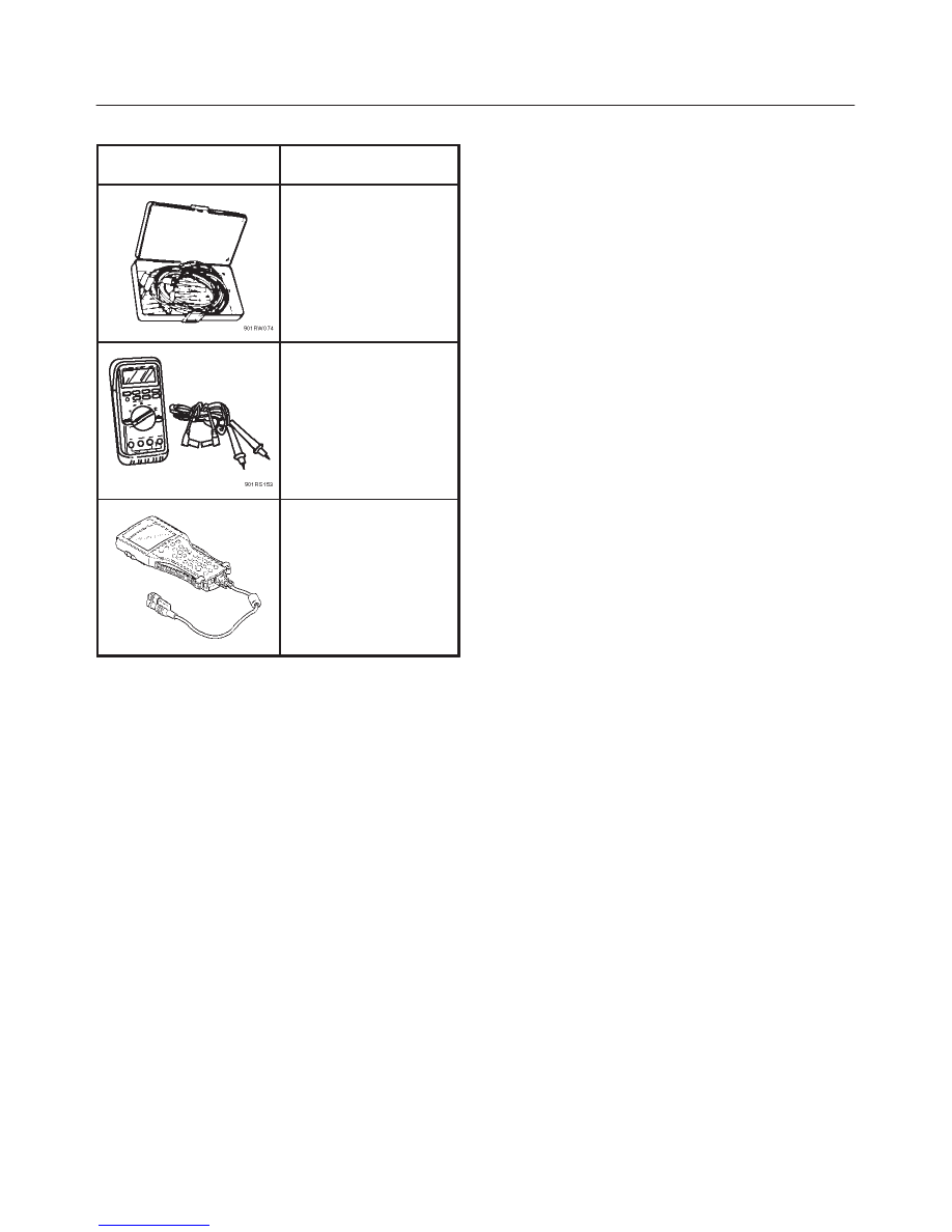
Special Tools
ILLUSTRATION
TOOL NO.
TOOL NAME
J–35616
Connector test adapter
kit
J–39200
High impedance
multimeter
7000086–ISU
Tech 2 Set
(1) PCMCIA Card
(2) SAE 16/19 Adapter
(3) DLC Cable
(4) Tech 2
5B–1
ANTI–LOCK BRAKE SYSTEM
RODEO
BRAKES
ANTI-LOCK BRAKE SYSTEM
CONTENTS
Service Precaution
5B–1
. . . . . . . . . . . . . . . . . . . . . .
Electronic Hydraulic Control Unit
5B–2
. . . . . . . . . .
Electronic Hydraulic Control Unit and
Associated Parts
5B–2
. . . . . . . . . . . . . . . . . . . . . .
Removal
5B–2
. . . . . . . . . . . . . . . . . . . . . . . . . . . . .
Disassembled View
5B–3
. . . . . . . . . . . . . . . . . . . .
Disassembly
5B–3
. . . . . . . . . . . . . . . . . . . . . . . . . .
Reassembly
5B–3
. . . . . . . . . . . . . . . . . . . . . . . . . .
Installation
5B–3
. . . . . . . . . . . . . . . . . . . . . . . . . . . .
Front Wheel Speed Sensor
5B–4
. . . . . . . . . . . . . . .
Front Wheel Speed Sensor and Associated
Parts
5B–4
. . . . . . . . . . . . . . . . . . . . . . . . . . . . . . . .
Removal
5B–4
. . . . . . . . . . . . . . . . . . . . . . . . . . . . .
Inspection and Repair
5B–4
. . . . . . . . . . . . . . . . . .
Installation
5B–4
. . . . . . . . . . . . . . . . . . . . . . . . . . . .
Rear Wheel Speed Sensor
5B–5
. . . . . . . . . . . . . . .
Removal
5B–5
. . . . . . . . . . . . . . . . . . . . . . . . . . . . .
Inspection and Repair
5B–5
. . . . . . . . . . . . . . . . . .
Installation
5B–5
. . . . . . . . . . . . . . . . . . . . . . . . . . . .
Service Precaution
WARNING: THIS VEHICLE HAS A SUPPLEMENTAL
RESTRAINT SYSTEM (SRS). REFER TO THE SRS
COMPONENT AND WIRING LOCATION VIEW IN
ORDER TO DETERMINE WHETHER YOU ARE
PERFORMING SERVICE ON OR NEAR THE SRS
COMPONENTS OR THE SRS WIRING. WHEN YOU
ARE PERFORMING SERVICE ON OR NEAR THE SRS
COMPONENTS OR THE SRS WIRING, REFER TO
THE SRS SERVICE INFORMATION. FAILURE TO
FOLLOW WARNINGS COULD RESULT IN POSSIBLE
AIR BAG DEPLOYMENT, PERSONAL INJURY, OR
OTHERWISE UNNEEDED SRS SYSTEM REPAIRS.
CAUTION: Always use the correct fastener in the
proper location. When you replace a fastener, use
ONLY the exact part number for that application.
ISUZU will call out those fasteners that require a
replacement after removal. ISUZU will also call out
the fasteners that require thread lockers or thread
sealant. UNLESS OTHERWISE SPECIFIED, do not
use supplemental coatings (Paints, greases, or other
corrosion inhibitors) on threaded fasteners or
fastener joint interfaces. Generally, such coatings
adversely affect the fastener torque and the joint
clamping force, and may damage the fastener. When
you install fasteners, use the correct tightening
sequence and specifications. Following these
instructions can help you avoid damage to parts and
systems.
Нет комментариевНе стесняйтесь поделиться с нами вашим ценным мнением.
Текст