Isuzu Rodeo UE. Manual — part 109
5B–2
ANTI–LOCK BRAKE SYSTEM
Electronic Hydraulic Control Unit
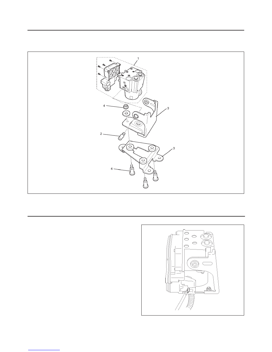
Electronic Hydraulic Control Unit and Associated Parts
350RW017
Legend
(1) EHCU
(2) Bolt
(3) Bracket
(4) Bolt and Nut
Removal
1. Remove brake pipes.
f
After disconnecting brake pipe, cap or tape the
openings of the brake pipe to prevent the entry of
foreign matter.
2. Remove three bracke fixing bolts.
3. Disconnect red clip from harness connector.
350RW018
5B–3
ANTI–LOCK BRAKE SYSTEM
4. Remove harness connector.
5. Remove EHCU ASM.
6. Remove EHCU.
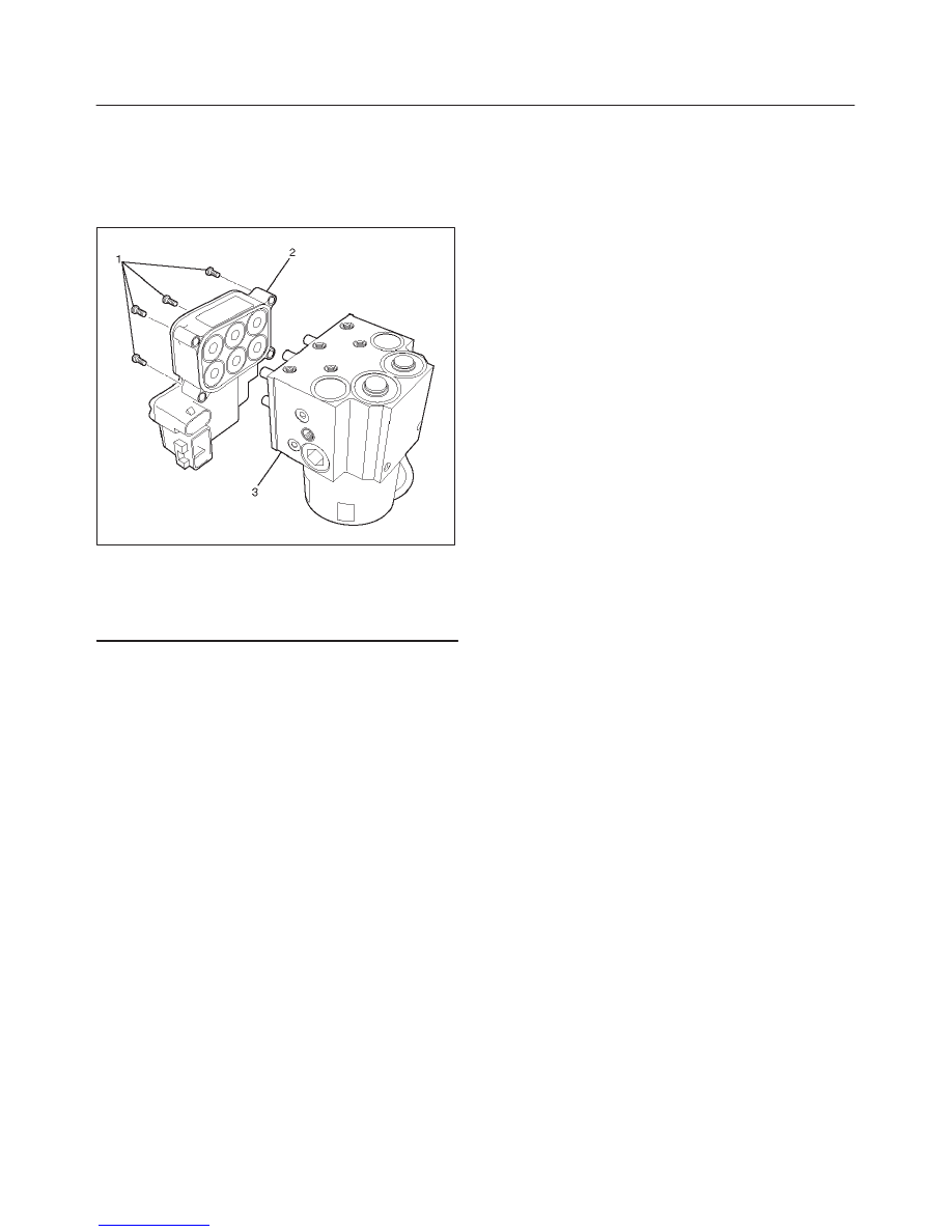
Disassembled View
350RW025
Legend
(1) Fixing Bolts
(2) Coil Integrated Module
(3) Hydraulic Unit (H/U)
Disassembly
1. Remove fixing bolts from EHCU.
2. Remove coil integrated module from hydraulic unit.
Reassembly
To reassembly, follow the disassembly steps in the
reverse order, noting the following points:
Torque:
Fixing bolts: 4.4 N·m (39 lb in)
Installation
To install, follow the removal steps in the reverse order,
noting the following points:
Torque:
Hydraulic unit fixing nuts : 22 N·m (16 lb ft)
Ground cable : 14 N·m (10 lb ft)
Brake pipe (joint bolts) : 16 N·m (12 lb ft)
f
After installing the hydraulic unit, bleed brakes
completely. See Section 5A “Hydraulic Brakes”.
5B–4
ANTI–LOCK BRAKE SYSTEM
Front Wheel Speed Sensor
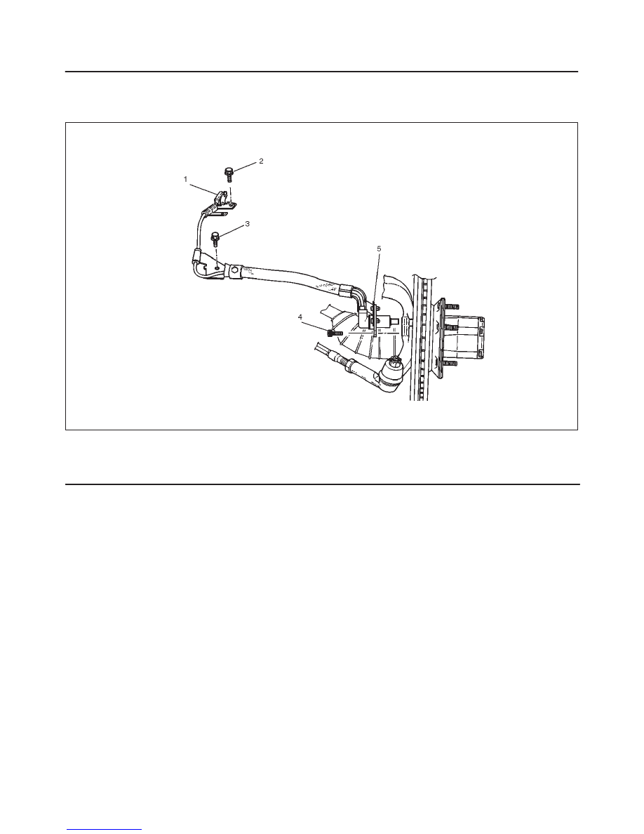
Front Wheel Speed Sensor and Associated Parts
350RS033
Legend
(1) Speed Sensor Connector
(2) Sensor Cable Fixing Bolt (Upper side)
(3) Sensor Cable Fixing Bolt (Lower side)
(4) Sensor Cable Fixing Bolt (Sensor side)
(5) Speed Sensor
Removal
1. Remove speed sensor connector.
2. Remove sensor cable fixing bolt (Upper side).
3. Remove sensor cable fixing bolt (Lower side).
4. Remove the speed sensor cable fixing bolt.
5. Remove speed sensor.
Inspection and Repair
1. Check the speed sensor pole piece for presence of
foreign materials; remove any dirt, etc.
2. Check the pole piece for damage; replace speed
sensor if necessary.
3. Check the speed sensor cable for short or open
circuit, and replace with a new one if necessary.
To check for cable short or open, bend or stretch the
cable while checking for continuity.
4. Check the sensor ring for damage including tooth
chipping, and if damaged, replace the sensor ring
assembly. Refer to removal of the sensor ring in
Section 4D “Front hub and disc”.
Installation
1. Install speed sensor and take care not to hit the speed
sensor pole piece during installation.
2. Install speed sensor fixing bolt and tighten the fixing
bolt to the specified torque.
Torque: 11 N·m (95 lb in)
3. Install speed sensor cable fixing bolt (Lower side) and
tighten the fixing bolt to the specified torque.
Torque : 24 N·m (18 lb ft)
4. Install speed sensor cable fixing bolt (Upper side) and
tighten the fixing bolt to the specified torque.
Torque : 6 N·m (52 lb ft)
NOTE: Confirm that a white line marked on the cable is
not twisted when connecting the speed sensor cable.
5. Install speed sensor connector.
5B–5
ANTI–LOCK BRAKE SYSTEM
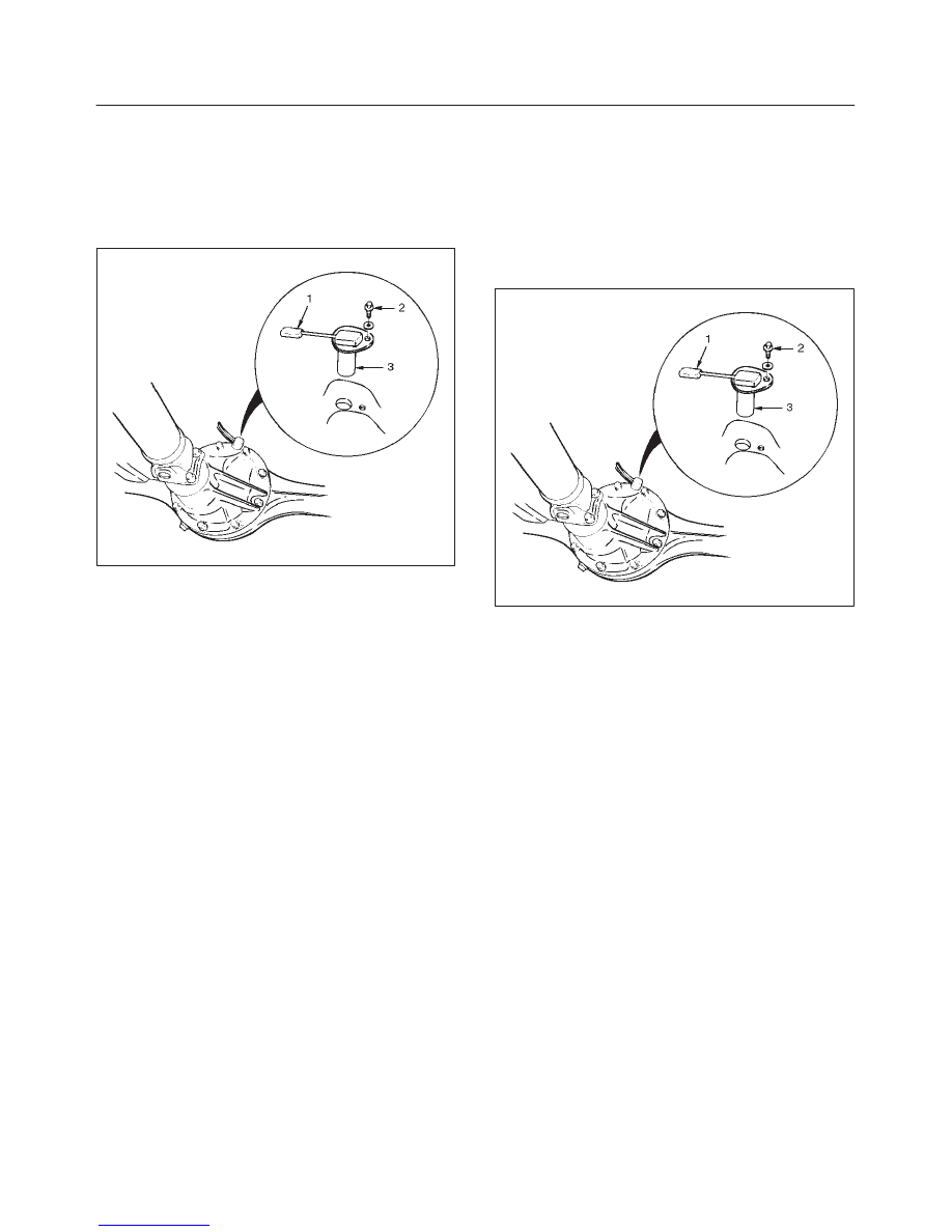
Rear Wheel Speed Sensor
Removal
1. Disconnect harness connector (1).
2. Remove sensor fixing bolt (2) .
3. Remove speed sensor (3).
350RW022
Inspection and Repair
1. Check speed sensor pole piece for presence of
foreign materials; remove any dirt, etc.
2. Check the pole piece for damage, and replace speed
sensor if necessary.
3. Check speed sensor cable for short or open, and
replace with a new one if necessary. To check for
cable short or open, bend or stretch the cable while
checking for continuity.
4. Check the sensor ring for damage including tooth
chipping, and if damaged, replace the axle shaft
assembly. Refer to removal of the sensor ring in
Section 4A2 “Differential (Rear)”.
Installation
1. Install speed sensor (3).
2. Tighten the sensor fixing bolt (2) to the specified
torque.
Torque : 11 N·m (95 lb in)
3. Connect harness connector (1).
350RW022
Нет комментариевНе стесняйтесь поделиться с нами вашим ценным мнением.
Текст