Isuzu Rodeo UE. Manual — part 107

5A–51
BRAKE CONTROL SYSTEM
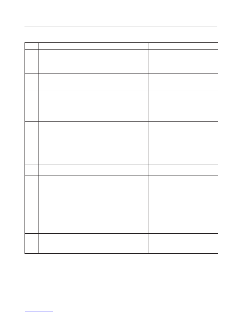
Chart B-22 Rear Speed Sensor Missing (DTC 63 (Flash out) / C0236, C0237 (Serial
communications))
Step
Action
Yes
No
1
1. Turn the key off.
2. Disconnect coil integrated module connector.
3. Measure the Rear speed sensor resistance between coil
integrated module connector (C-4) terminals 4 and 12.
Is the resistance between 1.2k and 2.0k ohms?
Go to Step 2
Go to Step 3
2
Is there play sensor/sensor rotor?
Repair.
Go to Step 6
Go to Step 4
3
Measure the rear speed sensor resistance at the sensor
connector.
Is the resistance between 1.2k and 2.0k ohms?
Repair harness
abnormality
between sensors
and coil
integrated
module.
Go to Step 6
Replace sensor.
Go to Step 6
4
Damage and powered iron sticking to sensor/sensor ring?
Repair.
Go to Step 6
Go to Step 5
5
Is sensor output normal? (Chart C-1-3 or TC-1)
Check for faults
in harness
between speed
sensor and coil
integrated
module.
Fault found:
repair, and
perform system
self-check.
No fault found:
replace EHCU.
Go to Step 6
Replace sensor.
Go to Step 6
6
1. Reconnect all components, ensure all components are
properly mounted.
2. Clear diagnostic trouble code.
Was this step finished?
Repeat the “Basic
diagnostic flow
chart”
Go to Step 6
NOTE: Even after repairing the faulty part the warning
light (W/L) does not go out if the vehicle is at a stop. Turn
the ignition switch to the ON position and drive the vehicle
at 12 km/h (8 mph) or higher to make sure that the
warning light goes out.
5A–52
BRAKE CONTROL SYSTEM
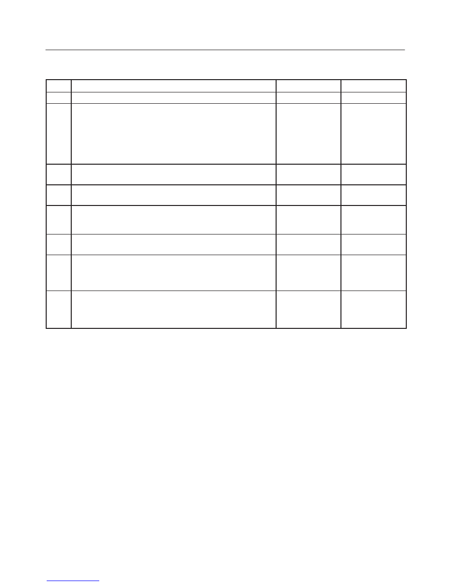
Chart B-23 Simultaneous Drop-out of Front Speed Sensor Signal (DTC 64 (Flash out) /
C0229 (Serial communications))
Step
Action
Yes
No
1
1. Turn the key off.
2. Disconnect coil integrated module connector.
3. Measure the FL speed sensor resistance between coil
integrated module connector (C-4) terminals 2 and 10.
Is the resistance between 2.0k and 2.8k ohms?
Go to Step 2
Go to Step 3
2
Measure the FR speed sensor resistance between coil integrated
module connector (C-4) terminals 3 and 11.
Is the resistance between 2.0k and 2.8 k ohms?
Go to Step 5
Go to Step 4
3
Measure the FL speed sensor resistance at the sensor connector.
Is the resistance between 2.0k and 2.8k ohms?
Repair harness
abnormality
between sensors
and coil
integrated
module.
Go to Step 2
Replace sensor.
Go to Step 2
4
Measure the FR speed sensor resistance at the sensor
connector.
Is the resistance between 2.0k and 2.8k ohms?
Repair harness
abnormality
between sensors
and coil
integrated
module.
Go to Step 5
Replace sensor.
Go to Step 5
5
Damage and powered iron sticking to sensor/sensor ring?
Repair.
Go to Step 6
Go to Step 6
6
Is there play sensor/sensor rotor?
Repair.
Go to Step 7
Go to Step 7
7
Is sensor output normal? (Chart C-1-1&C-1-2 or TC-1)
Check for faults
in harness
between speed
sensor and coil
integrated
module.
Fault found:
repair, and
perform system
self-check.
No fault found:
replace EHCU.
Go to Step 8
Replace sensor.
Go to Step 8
8
1. Reconnect all components, ensure all components are
properly mounted.
2. Clear diagnostic trouble code.
Was this step finished?
Repeat “Basic
diagnostic flow
chart”
Go to Step 8
NOTE: Even after repairing the faulty part the warning
light (W/L) does not go out if the vehicle is at a stop. Turn
the ignition switch to the ON position and drive the vehicle
at 12 km/h (8 mph) or higher to make sure that the
warning light goes out.
5A–53
BRAKE CONTROL SYSTEM
Chart B-24 Wheel Speed Input Abnormality (DTC 65 (Flash out) / C0238 (Serial
communications))
Step
Action
Yes
No
1
Using TECH 2?
Go to Step 2
Go to Step 3
2
1. Connect TECH 2.
2. Select Snap shot manual trigger.
3. With wheel speed data displayed, run the vehicle when speed
has arrived at 30 km/h (18 mph).
4. Check speed data on each wheel (refer to the criterion given
below). * 1
Is the abnormal sensor condition found?
Replace.
Go to Step 8
Go to Step 3
All the sensors
should follow the
following
flowchart (without
using TECH 2).
3
Is there play in sensor/sensor ring?
Repair.
Go to Step 8
Go to Step 4
4
Is there powdered iron sticking to sensor/sensor ring?
Repair.
Go to Step 8
Go to Step 5
5
Is there a broken tooth or indentation in sensor ring?
Replace sensor
ring.
Go to Step 8
Go to Step 6
6
Is there play in wheel bearing?
Adjust or repair.
Go to Step 8
Go to Step 7
7
Is the check wiring between sensor and coil integrated module
normal?
Replace EHCU.
Go to Step 8
Repair, and
perform system
self-check.
Go to Step 8
8
1. Reconnect all components, ensure all components are
properly mounted.
2. Clear diagnostic trouble code.
Was this step finished?
Repeat ‘Basic
diagnostic flow
chart”
Go to Step 8
Sensor Signal Abnormality Criteria using TECH 2
1. While driving, the speed of one or two wheels is 25%
or more higher or lower than that of the other wheels.
2. The speed of one or two wheels is 10 km/h (6 mph) or
more higher or lower than that of the other wheels.
3. During steady driving, wheel speed changes abruptly.
*1 The vehicle must run on a level paved road.
NOTE: Even after repairing the faulty part the warning
light (W/L) does not go out if the vehicle is at a stop.
Turn the ignition switch to the ON position and drive the
vehicle at 12 km/h (8 mph) or higher to make sure that the
warning light goes out.
It is important to verify that the correct tires are installed
on vehicle.

5A–54
BRAKE CONTROL SYSTEM
Unit Inspection Procedure
This section describes the following inspection proce-
dures referred to during “SYMPTOM DIAGNOSIS” and
“DIAGNOSIS BY ‘ABS’ WARNING LIGHT ILLUMINA-
TION PATTERN” :
without TECH 2
with TECH 2
Sensor Output Inspection
Chart C-1-1 to C-1-3
Chart TC-1
Chart C-1-1 FL Sensor Output Inspection Procedure
Step
Action
Yes
No
1
1. Turn the key off.
2. Disconnect coil integrated module connector.
3. Jack up the vehicle with all four wheels off the ground.
Measure the AC voltage between coil integrated module
connector terminals while turning FL wheel at a speed of 1
RPS:
Is the check between coil integrated module connector (C-4)
terminals 2 and 10 than under 200 mV?
Go to Step 2
OK.
Go to Step 3
2
1. Disconnect the wheel speed sensor.
2. Measure resistance between the wheel speed sensor
connector terminals 1 and 2.
Is the check between connector (C-13) terminals 1 and 2 within
2.0k - 2.8k ohms?
Connector is
faulty, or open or
short circuit of
harness between
wheel speed
sensor connector
and coil
integrated
module.
Inspect and
correct the
connector or
harness.
Go to Step 3
Wheel speed
sensor is faulty.
Replace the
wheel speed
sensor.
Go to Step 3
3
Reconnect all components, ensure all components are properly
mounted.
Was this step finished?
Repeat the “Basic
diagnostic flow
chart”
Go to Step 3
Нет комментариевНе стесняйтесь поделиться с нами вашим ценным мнением.
Текст