Isuzu Rodeo UE. Manual — part 576
8D–152
WIRING SYSTEM
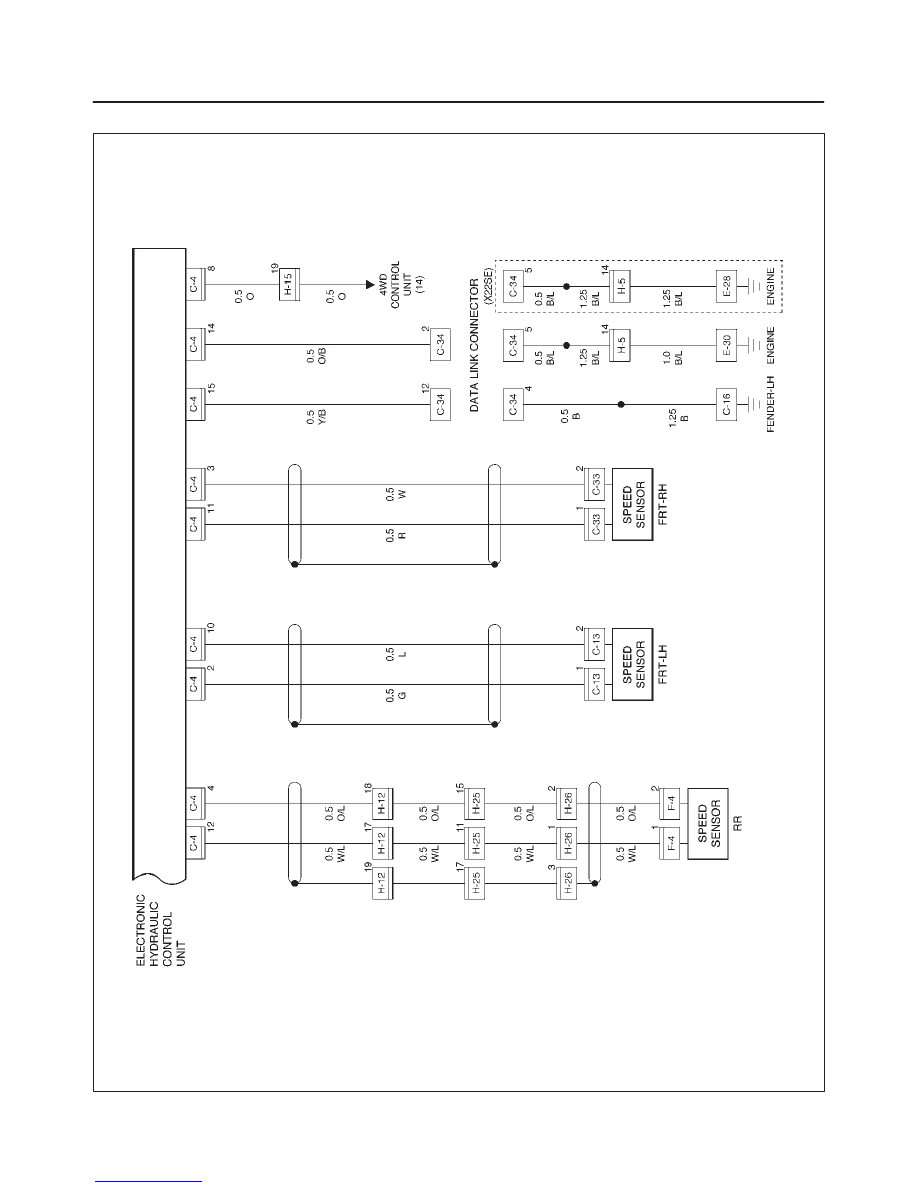
Circuit Diagram–3
D08RX109
8D–153
WIRING SYSTEM
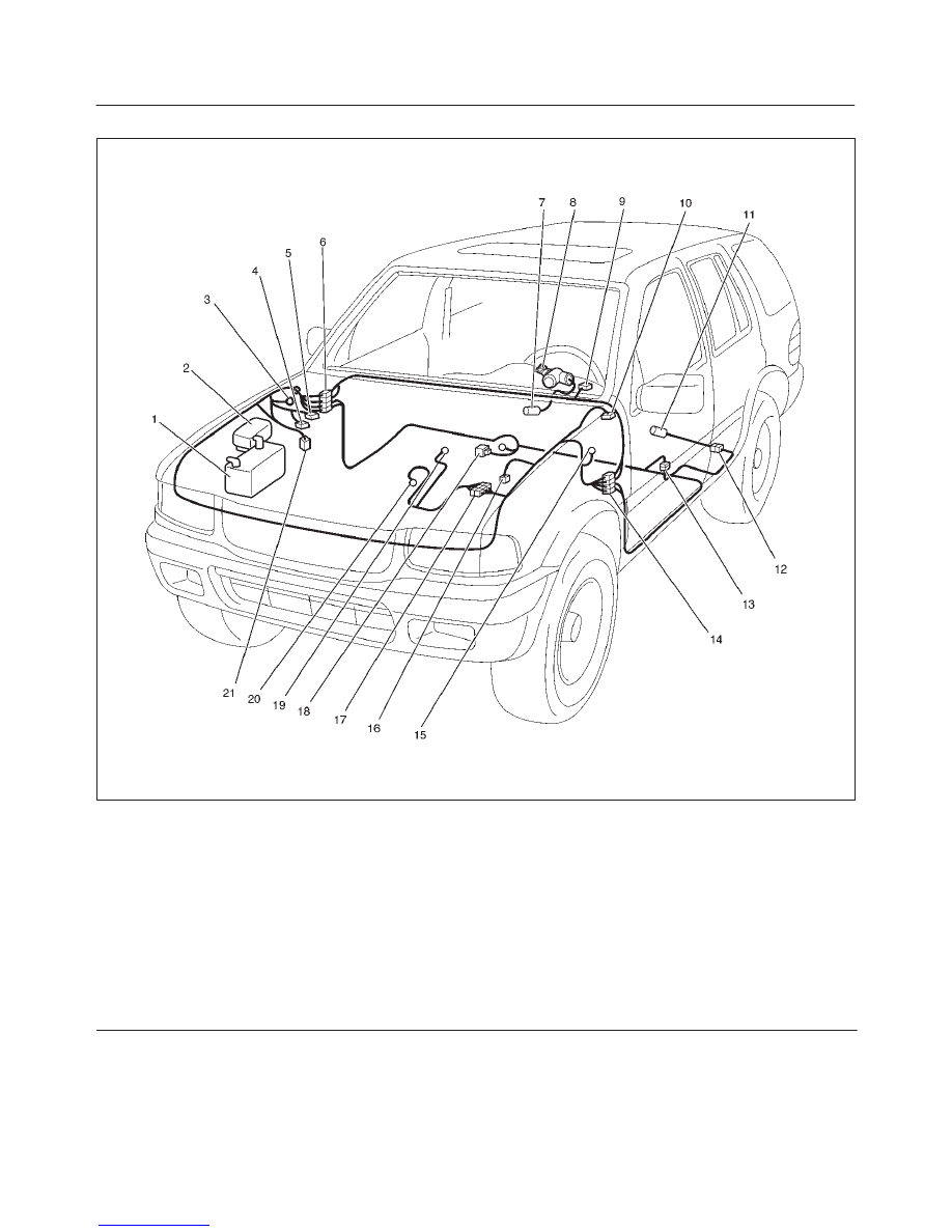
Parts Location
D08RX107
Legend
(1) Battery
(2) Relay & Fuse Box
(3) C–36
(4) C–5
(5) C–4
(6) H–12, 13, 14
(7) I–18
(8) Starter Switch
(9) I–1
(10) C–34
(11) F–4
(12) H–26
(13) H–25
(14) H–15
(15) C–16
(16) C–13
(17) H–5
(18) B–19
(19) E–30 (6VD1)
(20) E–28 (X22SE)
(21) C–33
8D–154
WIRING SYSTEM
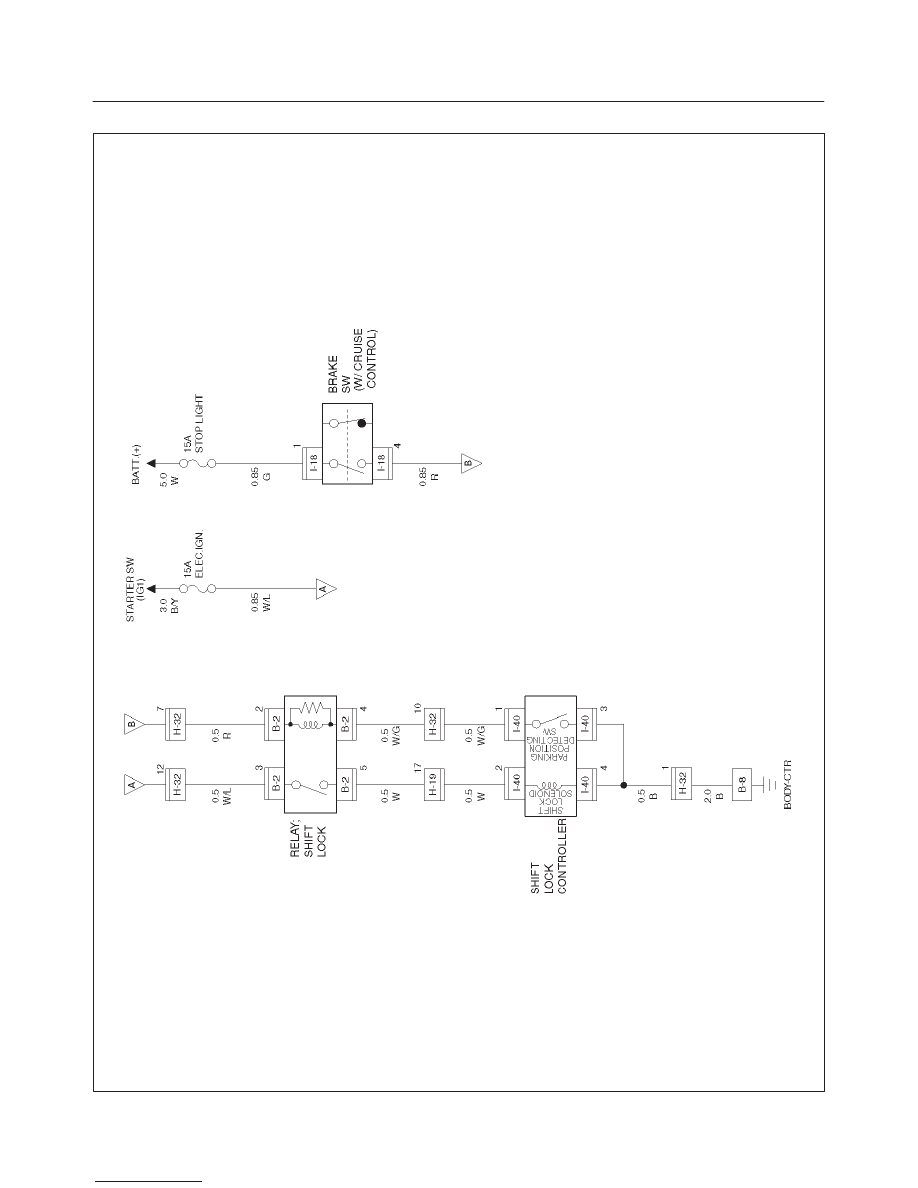
A/T Shift Lock
General Description
With the starter switch in the “ON” position and the shift
lever in “P” position, the shift lever cannot be shifted from
“P” to another position unless the brake pedal is
depressed. This is because, unless the brake pedal is
depressed, the solenoid pin underneath the shift lever
retracts and the link lever then locks the shift lever cam.
8D–155
WIRING SYSTEM
Circuit Diagram–1
D08RW241
Нет комментариевНе стесняйтесь поделиться с нами вашим ценным мнением.
Текст