Isuzu Rodeo UE. Manual — part 528
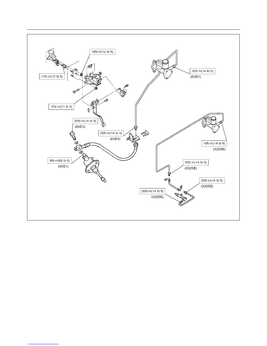
CLUTCH
7C–35
205RX001
7C–36
CLUTCH
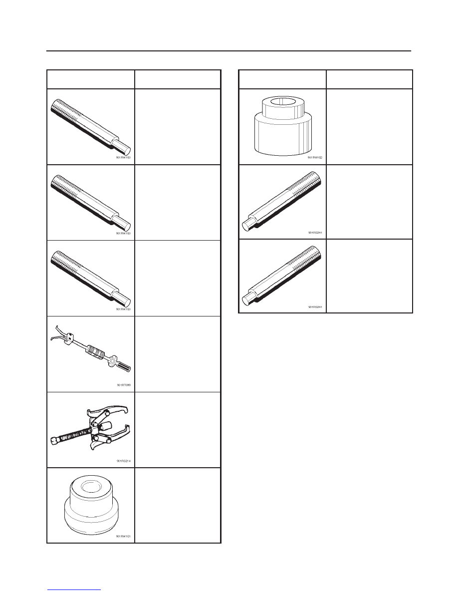
Special Tools
ILLUSTRATION
PART NO.
PART NAME
J–24547
Driven plate aligner
(6VD1)
J–33169
Driven plate aligner
(X22SE TREMEC)
J–42877
Driven plate aligner
(X22SE MUA)
J–5822 and J–23907
Pilot bearing remover
and Sliding hammer
J–22888
Bearing puller
J–2241–11
Adapter
ILLUSTRATION
PART NO.
PART NAME
J–26516–A
Crankshaft pilot bearing
installer (6VD1)
J–1522
Crankshaft pilot bearing
installer (X22SE)
J–8092
Driver handle
LIGHTING SYSTEM
8A–1
RODEO
BODY AND ACCESSORIES
LIGHTING SYSTEM
CONTENTS
Service Precaution
8A–1
. . . . . . . . . . . . . . . . . . . . . .
Headlight Bulb
8A–2
. . . . . . . . . . . . . . . . . . . . . . . . . .
Headlight Assembly
8A–2
. . . . . . . . . . . . . . . . . . . . .
Headlight Adjustment
8A–3
. . . . . . . . . . . . . . . . . .
Fog Light Bulb
8A–3
. . . . . . . . . . . . . . . . . . . . . . . . . .
Fog Light Assembly
8A–4
. . . . . . . . . . . . . . . . . . . . .
Fog Light Adjustment
8A–4
. . . . . . . . . . . . . . . . . .
Side Marker Light Bulb
8A–4
. . . . . . . . . . . . . . . . . . .
Front Combination Light Assembly
8A–5
. . . . . . . .
Taillight Bulb
8A–5
. . . . . . . . . . . . . . . . . . . . . . . . . . . .
License Plate Light Bulb (Bumper Type)
8A–6
. . . .
License Plate Light Bulb (Tailgate Type)
8A–6
. . . .
Stoplight Bulb
8A–7
. . . . . . . . . . . . . . . . . . . . . . . . . . .
High Mounted Stoplight Assembly
8A–7
. . . . . . . . .
High Mounted Stoplight Bulb
8A–8
. . . . . . . . . . . . . .
Backup Light Bulb
8A–8
. . . . . . . . . . . . . . . . . . . . . . .
Front Turn Signal Light Bulb
8A–9
. . . . . . . . . . . . . .
Rear Turn Signal Light Bulb
8A–9
. . . . . . . . . . . . . .
Dome Light Bulb
8A–10
. . . . . . . . . . . . . . . . . . . . . . . .
Courtesy Light Bulb
8A–10
. . . . . . . . . . . . . . . . . . . . . .
Spotlight Bulb
8A–11
. . . . . . . . . . . . . . . . . . . . . . . . . . .
Luggage Room Light Bulb
8A–11
. . . . . . . . . . . . . . . .
HVAC Bezel Illumination Light Bulb
8A–12
. . . . . . . .
Shift Lever Illumination Light Bulb (A/T)
8A–12
. . . .
Vanity Mirror Illumination Light Bulb
8A–13
. . . . . . . .
Starter Switch
8A–13
. . . . . . . . . . . . . . . . . . . . . . . . . . .
Lighting Switch (Combination Switch)
8A–14
. . . . . .
Dimmer·Passing Switch
(Combination Switch)
8A–14
. . . . . . . . . . . . . . . . . . .
Door Switch
8A–15
. . . . . . . . . . . . . . . . . . . . . . . . . . . .
Rear Defogger Switch
8A–15
. . . . . . . . . . . . . . . . . . .
Key Remind Switch (Starter Switch)
8A–16
. . . . . . .
Hazard Warning Light Switch
8A–16
. . . . . . . . . . . . .
Stoplight Switch
8A–16
. . . . . . . . . . . . . . . . . . . . . . . . .
Backup Light Switch (M/T)
8A–17
. . . . . . . . . . . . . . . .
Turn Signal Light Switch
(Combination Switch)
8A–17
. . . . . . . . . . . . . . . . . . .
Illumination Controller
8A–17
. . . . . . . . . . . . . . . . . . . .
Light and Bulb Specifications
8A–18
. . . . . . . . . . . . .
Service Precaution
WARNING: THIS VEHICLE HAS A SUPPLEMENTAL
RESTRAINT SYSTEM (SRS). REFER TO THE SRS
COMPONENT AND WIRING LOCATION VIEW IN
ORDER TO DETERMINE WHETHER YOU ARE
PERFORMING SERVICE ON OR NEAR THE SRS
COMPONENTS OR THE SRS WIRING. WHEN YOU
ARE PERFORMING SERVICE ON OR NEAR THE SRS
COMPONENTS OR THE SRS WIRING, REFER TO
THE SRS SERVICE INFORMATION. FAILURE TO
FOLLOW WARNINGS COULD RESULT IN POSSIBLE
AIR BAG DEPLOYMENT, PERSONAL INJURY, OR
OTHERWISE UNNEEDED SRS SYSTEM REPAIRS.
CAUTION: Always use the correct fastener in the
proper location. When you replace a fastener, use
ONLY the exact part number for that application.
ISUZU will call out those fasteners that require a
replacement after removal. ISUZU will also call out
the fasteners that require thread lockers or thread
sealant. UNLESS OTHERWISE SPECIFIED, do not
use supplemental coatings (Paints, greases, or other
corrosion inhibitors) on threaded fasteners or
fasteners joint interfaces. Generally, such coatings
adversely affect the fastener torque and the joint
clamping force, and may damage the fasteners.
When you install fasteners, use the correct
tightening sequence and specifications. Following
these instructions can help you avoid damage to
parts and systems.

8A–2
LIGHTING SYSTEM
Headlight Bulb
Removal
1. Disconnect the battery ground cable.
2. Remove the headlight bulb (2).
f
Disconnect the connector (3).
f
Release the socket retaining ring (1).
CAUTION: The halogen light bulb produces heat
and temperature rises high, therefore, if the glass
surface is contaminated it will be burnt by heat
leaving stains which will not come out. This may
reduce the illuminating power or damage the bulb
due to thermal deformation during evaporation. In
order to prevent this problem, do not touch the glass
surface with your fingers.
825RW062
Installation
To install, follow the removal steps in the reverse order.
Headlight Assembly
Removal
1. Disconnect the battery ground cable.
2. Remove the radiator grille (1).
f
Remove eight clips and a screw.
3. Remove the side marker light (3).
f
Remove three screws.
f
Disconnect the connector.
4. Remove the headlight assembly (2).
f
Disconnect the connector.
f
Remove four screws.
825RW063
Installation
To install, follow the removal steps in the reverse order.
CAUTION: After installing the headlight, be sure to
adjust the headlight aim.
Нет комментариевНе стесняйтесь поделиться с нами вашим ценным мнением.
Текст