Isuzu Rodeo UE. Manual — part 526
CLUTCH
7C–27
Removal
1. Disconnect the ground battery cable.
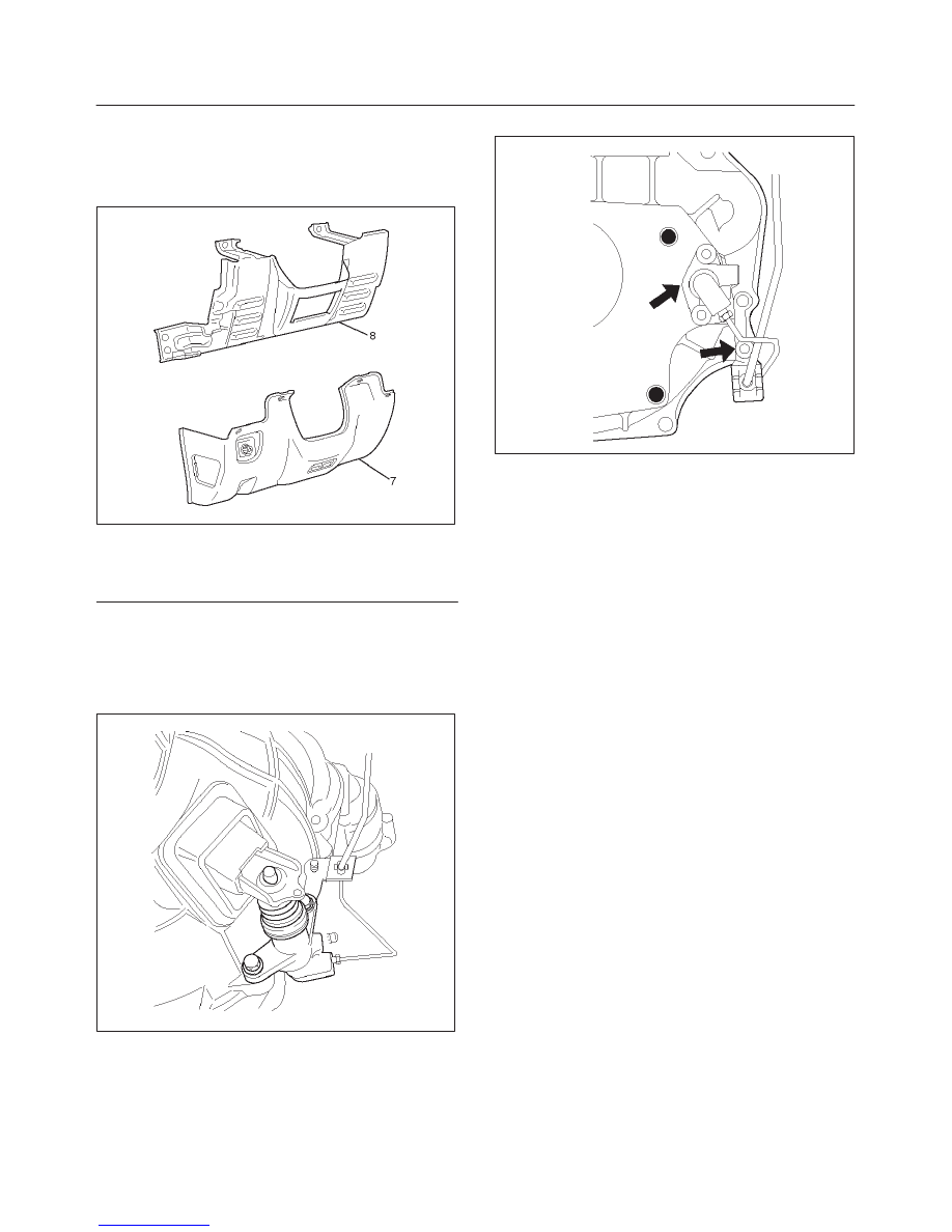
2. Remove the instrument panel lower cover (7) and
driver knee bolster panel assembly (8).
740RW023
Legend
(7) Driver Lower Cover
(8) Driver Knee Bolster Panel
3. Remove pin and jaw joint pin (1).
4. Remove pedal assembly and switch (2).
5. Remove oil line pipe (3).
6. Remove slave cylinder assembly (4).
X22SE MUA (4
×
4)
205RW001
TREMEC T5R
205RW002
7. Remove master cylinder assembly (5).
8. Remove oil line hose (6).
Inspection and Repair
Make necessary adjustments, repairs, and part
replacements if wear, damage or other problems are
discovered during inspection.
7C–28
CLUTCH
Installation
Clutch Pedal Adjustment
1. With clutch switch.
1. Disconnect clutch switch connector.
2. Loosen lock nut, then turn switch out until there is
a gap between the switch plunger and clutch
pedal.
208RW006
Legend
(7) Push Rod
(8) Clutch Switch
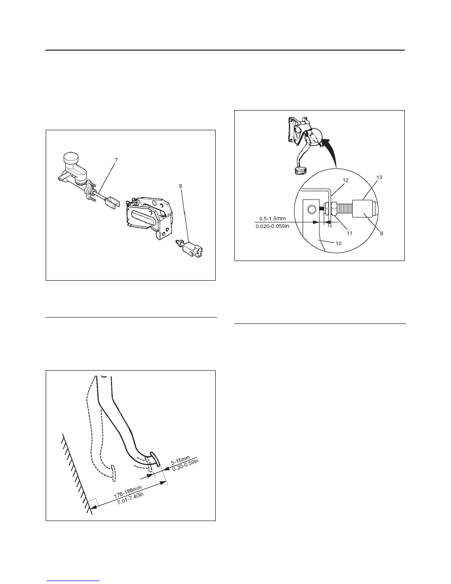
2. Loosen clutch master cylinder push rod lock nut. Turn
push rod by hand to set clutch pedal height to within
specification. Tighten push rod lock nut.
Clutch Pedal Height
178 – 188 mm (7.01 – 7.40 in)
F07RW026
3. With clutch switch.
1. Turn the clutch switch until the switch bolt just
touches the clutch pedal arm.
2. Adjust clutch switch by backing it out half a turn,
and measure the clearance between the clutch
pedal arm and the clutch switch bolt end.
F07RW027
Legend
(8) Clutch Switch
(10) Clutch Pedal Arm
(11) Lock Nut
(12) Bracket
(13) Back Out Switch 1/2 Turn
3. Lock the lock nut.
4. Connect clutch switch connector.
Clutch Switch and Clutch Pedal Clearance
0.5 – 1.5 mm (0.020 – 0.059 in)
4. After adjusting the clutch pedal height, push the
clutch pedal by hand to ensure the clutch pedal free
play is within specification.
Pedal Free Play
5 – 15 mm (0.20 – 0.59 in)
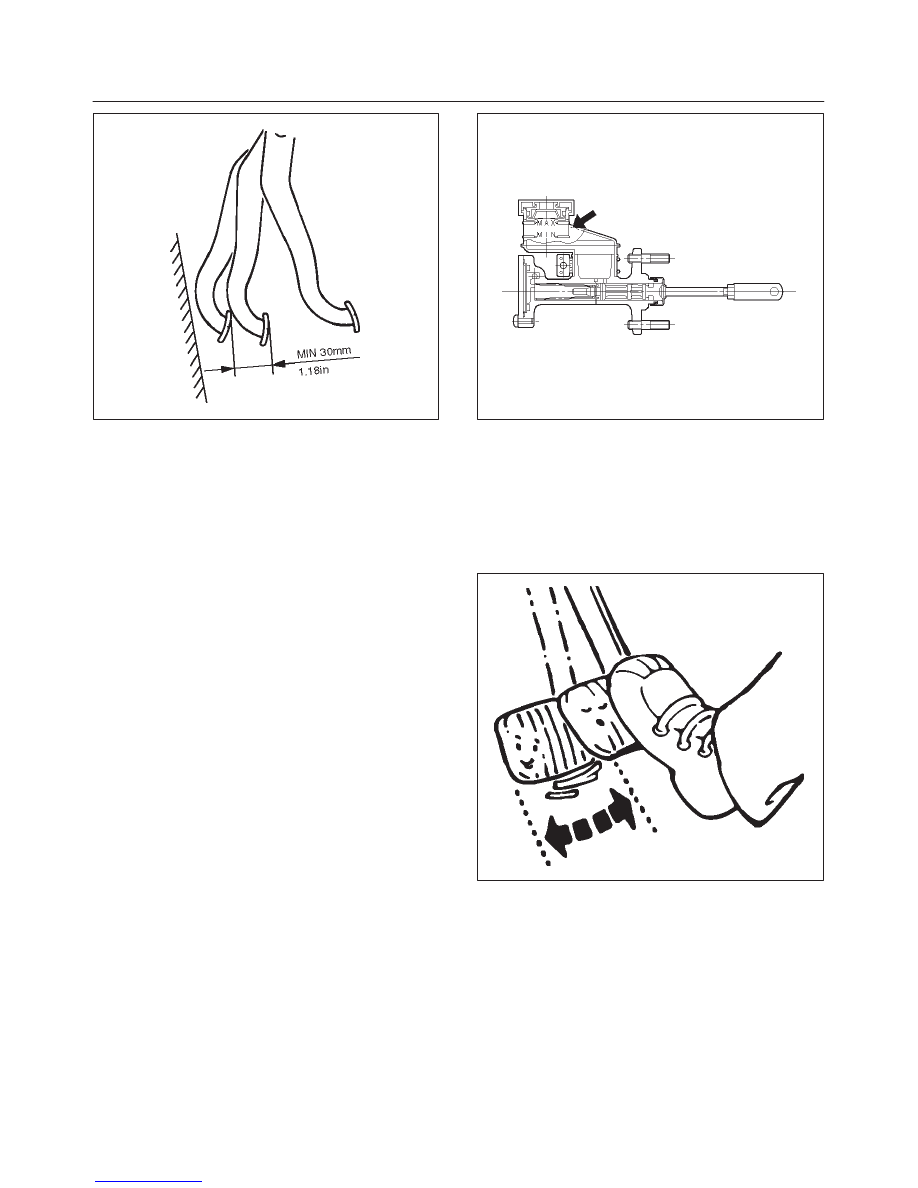
5. Perform clutch pedal engagement height inspection:
1. Operate the parking brake lever and block the
wheels.
2. Start the engine, fully step on the clutch pedal
slowly and move the shift lever 1st position.
3. With the engine idling, release the clutch pedal
slowly and measure its stroke – just prior to its
clutching position.
Clutch Pedal Engagement Height (H3)
MIN. 30 mm (1.18 in)
CLUTCH
7C–29
F07RW028
6. If the measured value exceeds the specified limit,
check the following points and repair if necessary:
f
Hydraulic circuit for fluid leakage or air in circuit.
f
Clutch disc warped.
f
Diaphragm spring weakened or tip of fingers worn.
f
Driven plate sticking on sprines.
f
Release bearing worn or damaged.
f
Master cylinder and slave cylinder worn.
Torque
f
Master cylinder to dash panel
16 N·m (12 lb ft)
f
Clutch pedal to dash panel
15 N·m (11 lb ft)
f
Master cylinder push rod to yoke
17 N·m (12 lb ft)
f
Clutch pipe to master cylinder
16 N·m (12 lb ft)
f
Clutch pipe to flex, hose
20 N·m (14 lb ft)
f
Slave cylinder to case
43 N·m (32 lb ft)
f
Slave cylinder bleeder screw
8 N·m (69 lb in)
f
Clutch pipe to slave cylinder
20 N·m (14 lb ft)
Bleeding
1. Check the level of clutch fluid in the reservoir and
replenish if necessary.
A07RW021
2. Bleeding the slave cylinder.
1. Remove the rubber cap from the bleeder screw
and wipe clean the bleeder screw. Connect a
vinyl tube to the bleeder screw and insert the
other end of the vinyl tube into a transparent
container.
2. Pump the clutch pedal repeatedly and hold it
depressed.
203RS005
3. Loosen the bleeder screw to release clutch fluid
with air bubbles into the container, then tighten
the bleeder screw immediately.
4. Release the clutch pedal carefully. Repeat the
above operation until air bubbles disappear from
the clutch fluid being pumped out into the
container. During the bleeding operation, keep
the clutch fluid reservoir filled to the specified
level. Reinstall the rubber cap.
7C–30
CLUTCH
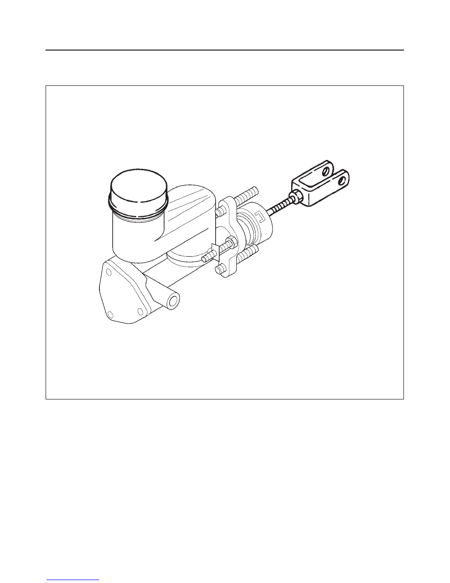
Master Cylinder
208RX001
NOTE: Disassembling and assembling the master
cylinder is not approved.
Нет комментариевНе стесняйтесь поделиться с нами вашим ценным мнением.
Текст