Isuzu Rodeo UE. Manual — part 525

CLUTCH
7C–23
Release Bearing
f
Visually check the release bearing for excessive play,
noise and breakage. If any of these conditions are
discovered, the release bearing must be replaced.
201RS011
f
When replacing the release bearing (4), replace both
the wedge collar (10) and wire ring (11) at the same
time.
201RS012
Legend
(2) Pressure Plate Assembly
(4) Release Bearing
(10) Wedge collar
(11) Wire Ring
Wedge Collar (10)
f
Visually check the surfaces of the wedge collar
making contact with the release bearing for excessive
wear and damage.
f
Replace exhibiting excessive wear or damage.
201RS013
Shift Fork
f
Visually check the surfaces of the shift fork making
contact with the release bearing for excessive wear
and damage.
f
Remove any minor stepping or abrasion from shift
fork with an oil stone. Replace exhibiting excessive
wear or damage.
201RS014

7C–24
CLUTCH
Installation
1. Clean and lubricate with grease.
2. Use the installer J–26516–A and driver handle
J–8092 to install the crankshaft bearing (7).
015RS046
3. Install the fulcrum bridge (6) to the transmission case.
Tighten three fulcrum bridge bolts to the specified
torque.
Torque: 38 N·m (28 lb ft)
201RS026
4. Apply molybdenum disulfide type grease to the pin
hole inner circumferences and thrust surfaces.
Attach the shift fork (5) to the fulcrum bridge (6) and
insert the pin from below of the fulcrum bridge. Install
the washer and snap pin.
201RS018
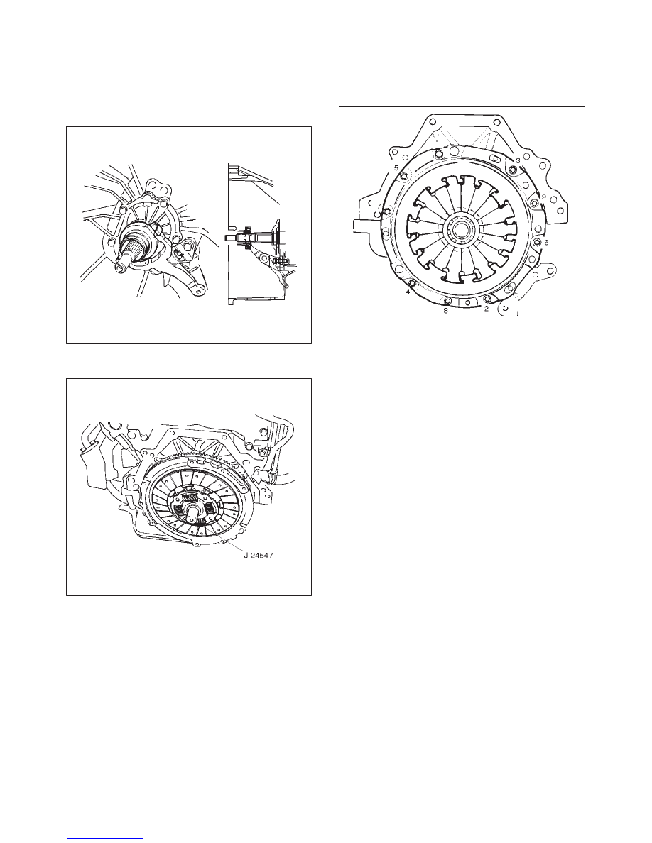
5. Apply molybdenum disulfide type grease to the areas
shown in the figure.
201RS015
CLUTCH
7C–25
Install the release bearing (4) in the proper direction.
NOTE: Ensure release bearing is properly positioned
during installation, as shown in the figure.
201RS019
6. Use the pilot aligner J–24547 to install the driven plate
assembly (3).
201RS016
7. Tighten the bolts holding the pressure plate assembly
(2) in the order shown in the figure.
201RS017
Torque: 18 N·m (13 lb ft)
8. Remove the aligner.
NOTE: Do not strike the aligner with a hammer to remove
it.
9. Install transmission assembly to the engine.
7C–26
CLUTCH
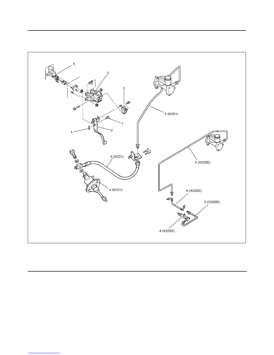
Clutch Control
Parts Location View
205RW004–1
Legend
(1) Pin and Jaw Joint Pin
(2) Pedal Assembly and Switch
(3) Oil Line Pipe
(4) Slave Cylinder Assembly
(5) Master Cylinder Assembly
(6) Oil Line Hose
Нет комментариевНе стесняйтесь поделиться с нами вашим ценным мнением.
Текст