Isuzu KB P190. Manual — part 1425

9A1-18 RESTRAINT CONTROL SYSTEM
DTC Will Clear When
Resistance value returns specified resistance value.
DTC Chart Test Description
Number(s) below refer to step number(s) on the
diagnostic chart:
2. This test determines whether the malfunction is in
the SRS control unit.
3. This test verifies proper connection of the yellow
connector.
4. This test checks for proper contact and/or corrosion
of the yellow connector terminals.
5. This test checks for a malfunctioning passenger air
bag assembly.
6. This test determines whether the malfunction is due
to a high resistance in the wiring.
Diagnostic Aids
An intermittent condition is likely to be caused by a poor
connection at the passenger air bag assembly harness
connector terminals “1” and “2”, SRS control unit
terminal “17” and “16”, or a poor wire to terminal
connection in circuits “Passenger Bag High” and
“Passenger Bag Low”. The test for this diagnostic
trouble code is only run while the “SRS” warning lamp is
performing the bulb check. When the scan tool “Clear
Codes” command is issued and the malfunction is still
present, the DTC will not reappear until the next ignition
cycle.
DTC B0015 (Flash Code 15) Passenger Air Bag Squib Circuit High Resistance
Step Action
Yes
No
1
Was the “SRS Diagnostic System Check” Performed?
Go to Step 2
Go to The “SRS
Diagnostic System
Check”
2
1. Check the passenger air bag squib circuit for open.
2. If a problem is found, repair as necessary.
Was a problem found?
Verify repair
Go to Step 3
3
1. Ignition switch is at “LOCK”.
2. Make sure the passenger air bag assembly yellow connector
located behind the glove box assembly is seated properly.
Is the yellow connector connected properly?
Go to Step 4
Seat passenger Air
Bag assembly
yellow connector
properly.
Go to Step 7
4
1. Disconnect and inspect the passenger air bag assembly
yellow connector located behind the glove box assembly.
2. If OK, reconnect the passenger air bag assembly connector.
3. Ignition switch is “ON”.
Is DTC B0015 current?
Go to Step 5
Go to Step 7
5
1. Ignition switch is at “LOCK”.
2. Disconnect the SRS coil and passenger air bag assembly,
yellow connector located at the base of the steering column
and behind the glove box assembly.
3. Connect a 5-8840-2421-0 SRS driver / passenger load tool
and appropriate adapters to the SRS coil and passenger air
bag assembly harness connectors.
4. Ignition switch is “ON”.
Is DTC B0015 Current?
Go to Step 6
Ignition switch
“LOCK”.
Replace the
passenger air bag
assembly.
Go to Step 7
RESTRAINT CONTROL SYSTEM 9A1-19
Step Action
Yes
No
6
1. Ignition switch is at “LOCK”.
2. There has been an increase in the total circuit resistance of
the passenger inflator deployment loop.
3. Use the high resolution ohmmeter mode of the DMM while
checking the circuits “Passenger Bag High” and “Passenger
Bag Low”, and the SRS control unit connector terminal “17”
and “16”, to locate the root cause.
Was a fault found?
Replace SRS
harness.
Go to Step 7
Go to Chart A
7
1. Reconnect all components and ensure all components are
properly mounted.
2. Clear the diagnostic trouble codes.
Is This step finished?
Repeat the “SRS
Diagnostic System
Check”
—
9A1-20 RESTRAINT CONTROL SYSTEM
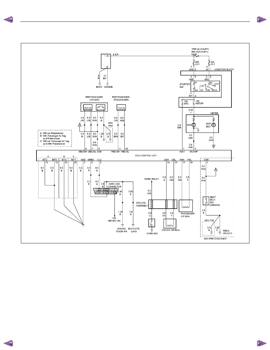
DTC B0016 (Flash Code 16) Passenger Air Bag Squib Circuit Low Resistance
RTW79ALF000301
Circuit Description
When the ignition switch is turned to “ON”, the SRS
control unit will perform tests to diagnose critical
malfunctions within itself. Upon passing these tests,
“Ignition 1”, and deployment loop voltages are
measured to ensure they are within their respective
normal voltage ranges. The SRS control unit then
proceeds with the “Resistance Measurement Test”. The
“Passenger Bag Low” terminal “16” is grounded through
a resistor and the passenger current source connected
to the “Passenger Bag High” terminal “17” and allows a
known amount of current to flow. By monitoring the
voltage difference between the “Passenger Bag High”
and “Passenger Bag Low”, the SRS control unit
calculates the combined resistance of the passenger air
bag assembly, harness wiring circuits “Passenger Bag
High” and “Passenger Bag Low” connector terminal
contact.
DTC Will Set When
The combined resistance of the passenger air bag
assembly, harness wiring circuits “Passenger Bag High”
and “Passenger Bag Low”, and connector terminal
contact is above a specified value. This test is run once
for each ignition cycle during the “Resistance
Measurement Test” when:
1. No “higher priority faults” are detected during “Turn–
ON”,
2. “Ignition 1” voltage is in the specified value.
Action Taken
The SRS control unit turns “ON” the “SRS” warning
lamp and sets a diagnostic trouble code.

RESTRAINT CONTROL SYSTEM 9A1-21
DTC Will Clear When
Resistance value returns to specified resistance value.
DTC Chart Test Description
Number(s) below refer to step number(s) on the
diagnostic chart:
2. This test determines whether the malfunction is in
the SRS control unit.
3. This test verifies connection of the yellow connector.
4. This test checks for proper operation of the shorting
clip on the yellow connector.
5. This test checks for a malfunctioning passenger air
bag assembly.
6. This test determines whether the malfunction is due
to shortening in the wiring.
Diagnostic Aids
An intermittent condition is likely to be caused by a short
between circuits “Passenger Bag High” and “Passenger
Bag Low” or a malfunctioning shorting clip on the
passenger air bag assembly which would require
replacement of the air bag assembly. The test for this
diagnostic trouble code is only run while the “SRS”
warning lamp is performing the bulb check. When the
scan tool “Clear Codes” command is issued and the
malfunction is still present, the DTC will not reappear
until the next ignition cycle.
DTC B0016 (Flash Code 16) Passenger Air Bag Squib Circuit Low Resistance
Step Action
Yes
No
1
Was the “SRS Diagnostic System Check” performed?
Go to Step 2
Repeat the “SRS
Diagnostic System
Check”
2
1. Check the passenger air bag squib circuit for short to voltage
or short to ground.
2. If a problem is found, repair as necessary.
Was a problem found?
Verify repair
Go to Step 3
3
1. Ignition switch is at “LOCK”.
2. Make sure the passenger air bag assembly yellow connector
located behind the glove box assembly is seated properly.
Is the yellow connector connected properly?
Go to Step 4
Seat passenger air
bag assembly
yellow connector
properly.
Go to Step 7
4
1. Disconnect and inspect the passenger air bag assembly
yellow connector located behind the glove box assembly.
2. If ok, reconnect the passenger air bag assembly connector.
3. Ignition switch is “ON”.
Is DTC B0016 Current?
Go to Step 5
Go to Step 7
5
1. Ignition switch is at “LOCK”.
2. Disconnect the SRS coil and passenger air bag assembly
yellow connector located at the base of the steering column
and behind the glove box assembly.
3. Connect 5-8840-2421-0 SRS driver/passenger load tool and
appropriate adapters to the SRS coil and the passenger air
bag assembly harness connectors.
4. Ignition switch is “ON”.
Is DTC B0016 current?
Go to Step 6
Ignition switch
“LOCK”.
Replace the
passenger air bag
assembly.
Go to Step 7
Нет комментариевНе стесняйтесь поделиться с нами вашим ценным мнением.
Текст