Isuzu KB P190. Manual — part 1423

9A1-10 RESTRAINT CONTROL SYSTEM
Chart A SRS Control Unit Integrity Check
RTW79ALF000301
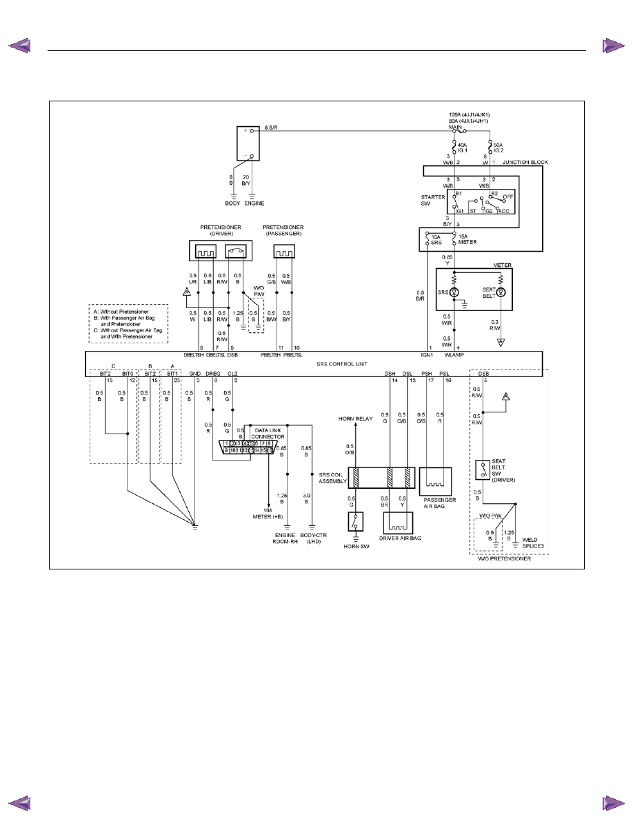
Circuit Description
When the SRS control unit recognizes that “Ignition 1”
voltage, applied to terminals “1”, is greater than 9 volts,
the “SRS” warning lamp is flashed 7 times to verify
operation. At this time the SRS control unit performs
“Turn–ON” tests followed by “Continuous Monitoring”
tests. When a malfunction is detected, the SRS control
unit sets a current diagnostic trouble code and
illuminates the “SRS” warning lamp. The SRS control
unit will clear current diagnostic trouble codes and move
them to a history file when the malfunction is no longer
detected and/or the ignition switch is cycled, except for
DTCs B0051 and B0055.
Chart Test Description
Number(s) below refer to step number(s) on the
diagnostic chart:
1. This test confirms a current malfunction. If no
current malfunction is occurring (history DTC set)
the “Diagnostic Aids” for the appropriate diagnostic
trouble code should be referenced. The SRS control
unit should not be replaced for a history diagnostic
trouble code.
2. This test checks for a malfunction introduced into the
SRS during the diagnostic process. It is extremely
unlikely that a malfunctioning SRS control unit would
cause a new malfunction to occur during the
diagnostic process.

RESTRAINT CONTROL SYSTEM 9A1-11
3. When all circuitry outside the SRS control unit has
been found to operate properly, as indicated by the
appropriate diagnostic chart, then and only then
should the SRS control unit be replaced.
Chart A SRS control unit Integrity Check
WARNING: DURING SERVICE PROCEDURES. BE VERY CAREFUL WHEN HANDLING A SRS CONTROL UNIT.
NEVER STRIKE OR JAR THE SRS CONTROL UNIT. NEVER POWER UP THE SRS WHEN THE SRS CONTROL
UNIT IS NOT RIGIDLY ATTACHED TO THE VEHICLE. ALL SRS CONTROL UNIT AND MOUNTING BRACKET
FASTENERS MUST BE CAREFULLY TORQUED AND THE ARROW MUST BE POINTING TOWARD THE FRONT
OF THE VEHICLE TO ENSURE PROPER OPERATION OF THE SRS. THE SRS CONTROL UNIT COULD BE
ACTIVATED WHEN POWERED WHILE NOT RIGIDLY ATTACHED TO THE VEHICLE WHICH COULD CAUSE
DEPLOYMENT AND RESULT IN PERSONAL INJURY
Step Action
Yes
No
1
1. This chart assumes that the “SRS Diagnostic System Check”
and either a symptom chart or a diagnostic trouble code chart
diagnosis has been performed. When all circuitry outside the
SRS control unit has been found to operate properly, as
indicated by the appropriate diagnostic chart, and the
symptom or DTC remains current, check the following.
2. Diagnostic procedures must be performed to verify the need
for SRS control unit replacement.
3. Ignition switch is at “LOCK”.
4. Reconnect all SRS components and ensure all components
are properly mounted.
5. Ensure the ignition switch has been in the “LOCK” position for
at least 15 seconds.
6. Note the “SRS” warning lamp as the ignition switch is turned
“ON”.
Does the warning lamp flash 7 times then go “OFF”?
The symptom or
DTC is no longer
occurring.
Clear SRS
diagnostic trouble
codes.
Repeat “SRS
Diagnostic System
Check”
Go to Step 2
2
Using a scan tool, request the diagnostic trouble code display.
Is the same symptom or DTC occurring that was occurring when
the “SRS Diagnostic System Check” was first performed?
Go to Step 3
Ignition switch
“LOCK”.
Go to the
appropriate chart
for the indicated
malfunction.
3
1. Clear the “SRS Diagnostic Trouble Codes”.
2. Ignition switch is in the “LOCK” position for at least two
minutes.
3. Note the “SRS” warning lamp as the ignition switch is turned
“ON”.
Does warning lamp flash 7 times then go “OFF”?
SRS is functional
and free of
malfunctions.
No further
diagnosis is
required.
Go to Step 4
Ignition switch
“LOCK”.
Replace SRS
control unit.
Go to Step 4
4
Reconnect all SRS components, ensure all components are
properly mounted.
Is this step finished?
Repeat the “SRS
Diagnostic System
Check”
—
9A1-12 RESTRAINT CONTROL SYSTEM
Chart B “SRS” Warning Lamp Comes “ON” Steady
RTW79ALF000301
Circuit Description
When the ignition switch is first turned “ON”, “Ignition 1”
voltage is applied from the “METER” fuse to the “SRS”,
warning lamp which is connected to “SRS Warning
Lamp”, terminal “4”. The “SRS” fuses apply system
voltage to the “Ignition 1” inputs, terminals “1”. The
SRS control unit responds by flashing the “SRS”
warning lamp 7 times. If “Ignition 1” is less than 9 volts,
the “SRS” warning lamp will come “ON” solid with no
DTCs set.
Chart Test Description
Number(s) below refer to step number(s) on the
diagnostic chart:
2. This test checks for an open in the “Ignition 1” circuit
to the SRS control unit.
3. This test checks for the voltage of “Ignition 1”.
4. This test determines whether the malfunction is a
short to ground in the SRS warning lamp circuit.

RESTRAINT CONTROL SYSTEM 9A1-13
Chart B “SRS” warning lamp comes “ON” Steady
Step Action
Yes
No
1
1. When measurements are requested in this chart use a 5-
8840-0366-0DMM with correct terminal adapter from 5-8840-
0385-0.
2. Ignition switch is at “LOCK”.
3. Connect the scan tool to the data link connector, following
directions as given in the scan tool instruction MANUAL.
4. Ignition switch is “ON”.
5. Request the SRS diagnostic trouble code display.
Does the scan tool indicate “No Data Received”?
Go to Step 2
Go to Step 3
2
1. Ignition switch is at “LOCK”.
2. Inspect the SRS control unit harness connector connection to
the SRS control unit.
Is it securely connected to the SRS control unit?
Ignition switch
“LOCK”.
Replace SRS
control unit.
Go to Step 5
Connect SRS
control unit
securely to de–
activate shorting
clip in SRS control
unit harness
connector.
Go to Step 5
3
Using scan tool, request the SRS data list.
Is “ignition” more than 9 volts?
Go to Step 4
Ignition switch
“LOCK”.
Replace SRS
control unit.
Go to Step 5
4
1. Ignition switch is at “LOCK”.
2. Disconnect the SRS coil and the passenger air bag assembly
yellow connector located at the base of the steering column
and behind the glove box assembly.
Disconnect the SRS control unit.
3. Disconnect the connector of the “SRS Warning Lamp” on the
instrument cluster.
4. Measure the resistance on the SRS control unit harness
connector as follow.
From terminals "3" and "23" to ground (ground) (without
the pretensioner)
From terminals "3" and "15" to ground (ground) (with the
pretensioner and the passenger air bag)
From terminals "3", "12" and "15" to ground (with the
pretensioner and without the passenger air bag)
Does 5-8840-0366-0DMM display “OL” (Infinite)?
Go to Chart A
Replace SRS
harness.
Go to Step 5
5
Reconnect all SRS components and ensure all components are
properly mounted.
Is this step finished?
Repeat the “SRS
Diagnostic System
Check”
—
Нет комментариевНе стесняйтесь поделиться с нами вашим ценным мнением.
Текст