Isuzu KB P190. Manual — part 1424

9A1-14 RESTRAINT CONTROL SYSTEM
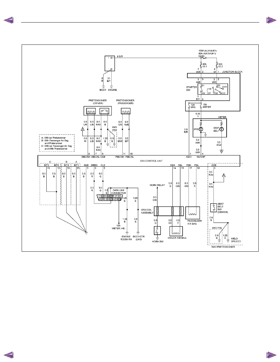
Chart C “SRS” Warning Lamp Does Not Come “ON” Steady
RTW79ALF000301
Circuit Description
When the ignition switch is first turned “ON”, “Ignition 1”
voltage is applied from the “METER” fuse to the “SRS”
warning lamp which is connected to the “SRS Warning
Lamp”, terminal “4”. The “SRS” fuse applies system
voltage to the “Ignition 1” inputs, terminals “35”. The
SRS control unit responds by flashing the “SRS”
warning lamp seven times. If “Ignition 1” is more than
16 volts, the “SRS” warning lamp will still be “OFF” solid
with no DTCs set.
Chart Test Description
Number(s) below refer to step number(s) on the
diagnostic chart:
1. This test decides whether power is available to the
SRS control unit warning lamp power feed circuit.
2. This test determines whether the voltage is present
in the warning lamp circuit.
3. This test determines if the malfunction is in the
instrument cluster.
4. This test checks for open in the warning lamp
circuitry.
5. This test isolates the SRS warning lamp circuit and
checks for a short in the SRS warning lamp circuit to
B+.
8. This test checks for a short from the SRS control
unit warning lamp power feed circuit to ground.
9. This test determines whether the short to ground is
due to a short in the wiring.
RESTRAINT CONTROL SYSTEM 9A1-15
Chart C “SRS” Warning Lamp Does Not Come “ON” Steady
Step Action
Yes
No
1
1. When measurements are requested in this chart, use a 5-
8840-0366-0DMM with a correct terminal adapter from 5-
8840-0385-0.
2. Ignition switch is at “LOCK”.
3. Remove and inspect the “METER” fuse to the “SRS” warning
lamp.
Is the fuse good?
Go to Step 2
Go to Step 7
2
1. Ignition switch is at “LOCK”.
2. Disconnect the SRS coil and passenger air bag assembly
yellow connector which is located at the base of the steering
column and behind the glove box assembly.
3. Disconnect the SRS control unit.
4. Ignition switch is “ON”.
5.
Measure the voltage on the SRS control unit harness
connector from the terminal “4” to terminal “3” (ground).
Is system voltage present on terminal “4”?
Go to Step 4
Go to Step 3
3
1. Ignition switch is at “LOCK”.
2. Remove instrument meter cluster.
3. Check for proper connection to instrument cluster at the SRS
warning lamp circuit terminal.
4. If ok, then remove and inspect the “AIR BAG” bulb.
Is the bulb good?
Go to Step 5
Replace bulb.
Go to Step 6
4
1. Ignition switch is at “LOCK”.
2. Disconnect instrument meter cluster harness connector.
3. Ignition switch is “ON”.
4.
Measure the voltage on the SRS control unit harness
connector from terminal “4” to terminal “3” (ground).
Is the voltage 1 volt or less?
Go to Chart A
Replace SRS
harness.
Go to Step 6
5
1. Install the bulb.
2. Measure the resistance from the instrument meter cluster
harness connector SRS warning lamp circuit terminal to the
SRS control unit harness connector terminal “4”.
Is the resistance 5.0 ohms or less?
Service instrument
meter cluster.
Install instrument
meter cluster.
Go to Step 6
Replace SRS
harness.
Go to Step 6
6
Reconnect all SRS components and ensure all components are
properly mounted.
Is this step finished?
Repeat the “SRS
Diagnostic System
Check”
Go to Step 6
7
Perform chart C.
Is this step finished?
Go to Step 8
Go to Step 1
8
1. Replace the “METER” fuse.
2. Ignition switch is “ON”. Wait 10 Seconds then ignition switch
is at “LOCK”.
3. Remove and inspect the “METER” fuse.
Is the fuse good?
Install “METER”
fuse.
Go to Step 10
Go to Step 9
9A1-16 RESTRAINT CONTROL SYSTEM
Step Action
Yes
No
9
1. Disconnect the SRS coil and the passenger air bag assembly
yellow connectors located at the base of the steering column
and behind the glove box assembly.
2. Disconnect the SRS control unit.
3. Replace the “METER” fuse.
4. Ignition switch is “ON”-wait 10 seconds.
5. Ignition switch is at “LOCK”.
6. Remove and inspect the “METER” fuse.
Is the fuse good?
Install “METER”
fuse.
Go to Chart A
Replace SRS
harness.
Replace “METER”
fuse.
Go to Step 10
10
Reconnect all the SRS components and ensure all the
components are properly mounted.
Is this step finished?
Repeat the “SRS
Diagnostic System
Check”
—
RESTRAINT CONTROL SYSTEM 9A1-17
DTC B0015 (Flash Code 15) Passenger Air Bag Squib Circuit High Resistance
RTW79ALF000301
Circuit Description
When the ignition switch is turned to “ON”, the SRS
control unit will perform tests to diagnose critical
malfunctions within itself. Upon passing these tests,
“Ignition 1”, and deployment loop voltages are
measured to ensure they are within their respective
normal voltage ranges. The SRS control unit then
proceeds with the “Resistance Measurement Test”.
The “Passenger Bag Low” terminal “16” is grounded
through a resister and the passenger current source
connected to the “Passenger Bag High” terminal “17”
and allows a known amount of current to flow. By
monitoring the voltage difference between the
“Passenger Bag High” and “Passenger Bag Low” the
SRS control unit calculates the combined resistance of
the passenger air bag assembly, harness wiring circuits
“Passenger Bag High” and “Passenger Bag Low”
connector terminal contact.
DTC Will Set When
The combined resistance of the passenger air bag
assembly, harness wiring circuits “Passenger Bag High”
and “Passenger Bag Low”, and connector terminal
contact is above a specified value. This test is run once
for each ignition cycle during the “Resistance
Measurement Test” when:
1. No “higher priority faults” are detected during “Turn–
ON”,
2. “Ignition 1” voltage is in the specified value.
Action Taken
The SRS control unit turns “ON” the “SRS” warning
lamp and sets a diagnostic trouble code.
Нет комментариевНе стесняйтесь поделиться с нами вашим ценным мнением.
Текст