Isuzu KB P190. Manual — part 1238
8A-14 ELECTRICAL-BODY AND CHASSIS
Distinction of Circuit by Wire Base Color
Base color
Circuits
Base color
Circuits
B
Starter circuit and grounding circuit
Y
Instrument circuit
W
Charging circuit
L, O, BR,
R
Lighting circuit
LG, GR,
Other circuits
G
Signal circuit
P, LB, V
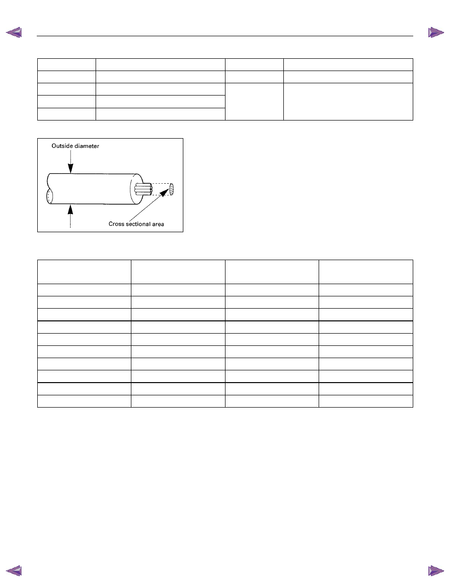
Wire Size
Wire size is specified with the metric gauge system.
The metric gauge system gives the wire size in cross sectional
area measured in square millimeters.
Wire Size Specifications
Nominal size
Cross sectional area
(mm
2
)
Outside diameter
(mm)
Allowable current
(A)
0.3 0.372 1.8
9
0.5 0.563 2.0 12
0.85 0.885 2.2
16
1.25 1.287 2.5
21
2 2.091 2.9 28
3 3.296 3.6 37.5
5 5.227 4.4 53
8 7.952 5.5 67
15 13.36 7.0 75
20 20.61 8.2 97
ELECTRICAL-BODY AND CHASSIS 8A-15
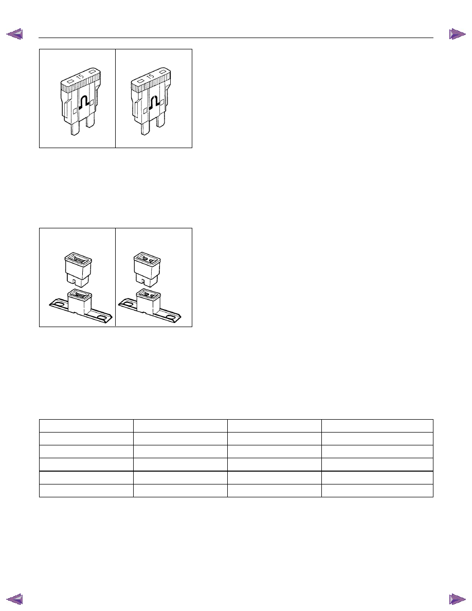
Normal
Blown
FUSE
Fuses are the most common form of circuit protection used in
vehicle wiring.
A fuse is a thin piece of wire or strip of metal encased in a
glass or plastic housing.
It is wired in series with the circuit it protects.
When there is an overload of current in a circuit, such as a
short of a ground, the wire or metal strip is designed to burn
out and interrupt the flow of current.
This prevents a surge of high current from reaching and
damaging other components in the circuit.
Determine the cause of the overloaded before replacing the
fuse.
Never replace a blown fuse with a fuse of a different amperage
specification.
Doing so can result in an electrical fire or other serious circuit
damage.
A blown fuse is easily identified.
Normal
Blown
FUSIBLE LINK
The fusible link is primarily used to protect circuits where high
amounts of current flow and where is would not be practical to
use a fuse.
For example, the starter circuit.
When a current overload occurs, the fusible link melts open
and interrupts the flow of current so as to prevent the rest of
the wiring harness from burning.
Determine the cause of the overload before replacing the
fusible link.
The replacement fusible link must have the same amperage
specification as the original fusible link.
Never replace a blown fusible link with fusible link of a different
amperage specification.
Doing so can result in an electrical fire or other serious circuit
damage.
A blown fusible link is easily identified.
Fusible Link Specifications
Type
Rating
Case Color
Maximum Circuit Current (A)
Connector 30A
Pink
15
Connector 40A Green
20
Bolted 50A Red
25
Bolted 60A Yellow
30
Bolted 80A Black
40

8A-16 ELECTRICAL-BODY AND CHASSIS
RELAY
Battery and load location may require that a switch be placed
some distance from either component.
This means a longer wire and a higher voltage drop
1
. The
installation of a relay between the battery and the load reduces
the voltage drop
2
.
Because the switch controls the relay, amperage through the
switch can be reduced.
Relay Specifications and Configurations
Name/
Color
Rated
voltage/ Coil
resistance
Internal circuit
Name/
color
Rated
Voltage/Coil
resistance
Internal circuit
1T
(MICRO
ISO)
/Black
12V
Approx. 92
Ω
Minimum
operating
voltage: 7V at
20
°C (77°F)
1M (MINI
ISO)
/Black
12V Approx.
94
Ω Minimum
operating
voltage: 7V at
20
°C (77°F)
1M
(MICRO
ISO)
/Black
12V
Approx. 132-3
Ω Minimum
operating
voltage: 7V at
20
°C (77°F)
1M
(power)/
Black
12V Approx.
94
Ω Minimum
operating
voltage: 7V at
20
°C (77°F)
* Relay contact shown in the wiring diagram indicates condition before actuation.
ELECTRICAL-BODY AND CHASSIS 8A-17
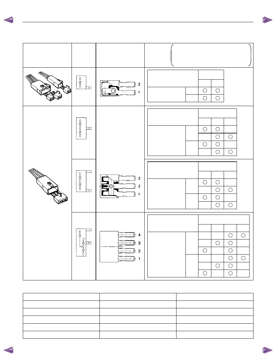
DIODE
Diode Specifications and Configurations
SHAPE
MARK/
COLOR
CONSTRUCTION
CHECKING
THERE SHOULD BE CONTINUITY IN
EITHER A OR B WHEN A CIRCUIT
TESTER IS CONNECTED WITH
DIODE TERMINAL
BLACK
2
1
CONNECTION
A
+
-
PATTERN
B
-
+
TERMINAL NO.
BLACK
3
2
1
-
+
CONNECTION
+
-
PATTERN
+
-
-
+
B
A
TERMINAL NO.
BLACK
3
2
1
-
+
CONNECTION
+
-
PATTERN
+
-
-
+
B
A
TERMINAL NO.
BLACK
4
3
2
1
+
-
A
-
+
CONNECTION
-
+
PATTERN
-
+
B
+
-
+
-
TERMINAL NO.
Maximum Rating (Temp.=25
°°°°C)
Items
Rating
Remarks
Peak reverse voltage
400V
Transient peak reverse voltage
500V
Average output current
1.5A
Temp.=40
°C
Working ambient temperature
-30
°C∼80°C
Storage temperature
-40
°C∼100ßC
Нет комментариевНе стесняйтесь поделиться с нами вашим ценным мнением.
Текст