Isuzu KB P190. Manual — part 1237
8A-10 ELECTRICAL-BODY AND CHASSIS
Solder
Apply 60/40 rosin core solder to the opening in the back of the
clip.
Follow the manufacturer’s instructions for the solder equipment
you are using.
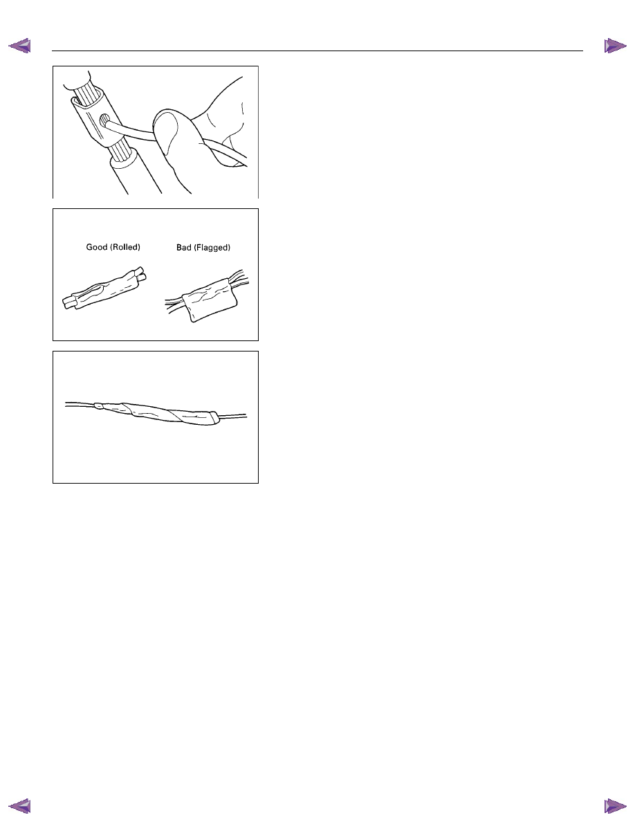
Tape the Splice
Center and roll the splicing tape.
The tape should cover the entire splice.
Roll on enough tape to duplicate the thickness of the insulation
on the existing wires.
Do not flag the tape.
Flagged tape may not provide enough insulation, and the
flagged ends will tangle with the other wires in the harness.
If the wire does not belong in a conduit or other harness
covering, tape the wire again.
Use a winding motion to cover the first piece of tape.
ELECTRICAL-BODY AND CHASSIS 8A-11
SYMBOLS AND ABBREVIATIONS
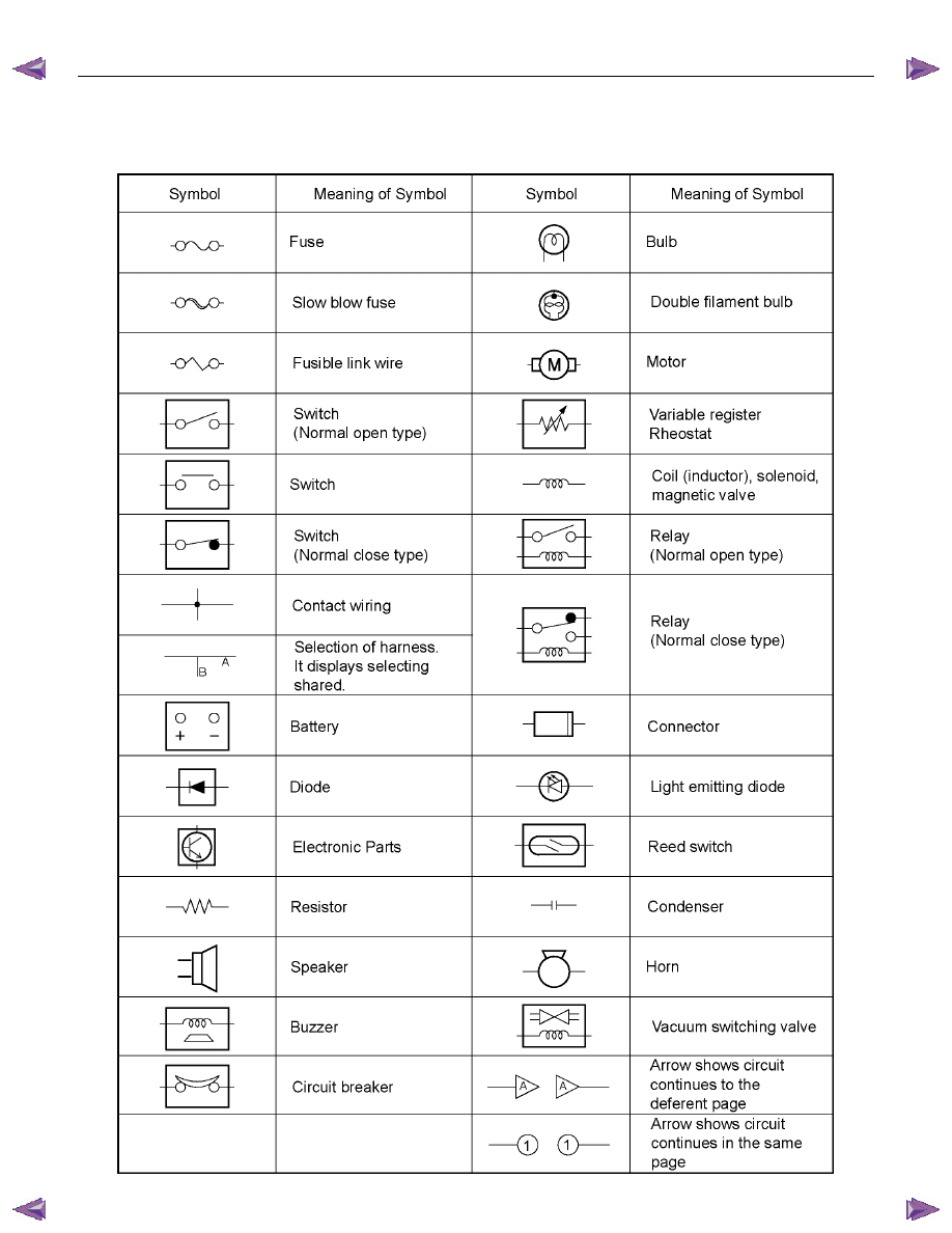
SYMBOLS

8A-12 ELECTRICAL-BODY AND CHASSIS
ABBREVIATIONS
Abbreviation
Meaning of abbreviation
Abbreviation
Meaning of abbreviation
A Ampere
(S)
kW Kilowatt
ABS
Anti-lock brake system
LH
Left hand
ASM
Assembly
LWB
Long wheel base
AC
Alternating current
MPI
Multipart fuel injection
A/C
Air conditioner
M/T
Manual transmission
ACC Accessories
PA Passenger
CARB
Carburetor
PIM
Power train interface module
C/B Circuit
breaker
PJT Projector
CKP
Crankshaft position
QOS
Quick On Start system
CSD
Cold start device
RH
Right hand
DIS
Direct ignition system
RR
Rear
DR
Driver
RWAL
Rear wheel anti-lock brake system
DRM
Data Recording Module
SCV
Suction control valve
EHCU
Electronic Hydraulic control Unit
SRS
Supplemental restraint system
ECGI
Electronic control gasoline injection
ST
Start
ECM
Engine control module
STD
Standard
ECU
Electronic control unit
SW
Switch
EFE
Early fuel evaporation
SWB
Short wheel base
EGR
Exhaust gas recirculation
TCM
Transmission control module
2WD
Two-wheel drive
TCCM
Transfer case control module
4WD Four-wheel
drive
V Volt
FL
Fusible link
VSV
Vacuum switching valve
FRT Front
W Watt
(S)
H/L
Headlight
WOT
Wide open throttle
W/ With
HVAC
Heater, Ventilation, and Air
Conditioning
W/O Without
IC
Integrated circuit
W/S
Weld Splice
IG Ignition
ELECTRICAL-BODY AND CHASSIS 8A-13
PARTS FOR ELECTRICAL CIRCUIT
WIRING
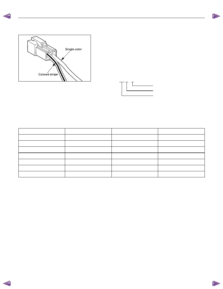
Wire Color
All wires have color-coded insulation.
Wires belonging to system's main harness will have a single
color.
Wires belonging to a system's sub-circuits will have a colored
stripe.
Striped wires use the following code to show wire size and
colors.
Example: 0.5 G / R
Red (Stripe color)
Green (Base color)
Wire size (0.5mm
2
)
Abbreviations are used to indicate wire color within a circuit
diagram.
Refer to the following table.
Wire Color-Coding
Color-Coding
Meaning
Color-Coding
Meaning
B Black BR
Brown
W White LG
Light
green
R Red GR
Gray
G Green P Pink
Y Yellow SB
Sky
blue
L Blue V Violet
O Orange
Нет комментариевНе стесняйтесь поделиться с нами вашим ценным мнением.
Текст