Isuzu KB P190. Manual — part 1236
8A-6 ELECTRICAL-BODY AND CHASSIS
Connecting the Connectors
Firmly grasp both sides (male and female) of the connector.
Be sure that the connector pins and pin holes match.
Be sure that both sides of the connector are aligned with each
other.
Firmly but carefully push the two sides of the connector
together until a distinct click is heard.
Connector Inspection
Use a circuit tester to check the connector for continuity.
Insert the test probes from the connector wire side.
CAUTION
Never insert the circuit tester test probes into the
connector open side to test the continuity.
Broken or open connector terminals will result.
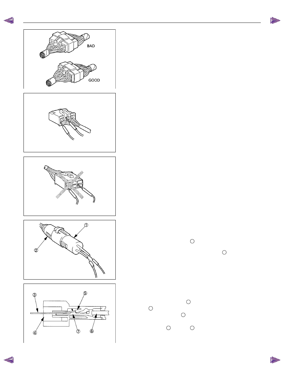
Waterproof Connector Inspection
It is not possible to insert the test probes into the connector
wire side of a waterproof connector.
Use one side of a connector
1
with its wires cut to make the
test.
Connect the test connector to the connector
2
to be tested.
Connect the test probes to the cut wires to check the connector
continuity.
Connector Pin Removal
Connector Housing Tang Lock Type
5. Insert a slender shaft
3
into the connector housing open
end
4
.
5. Push the tang lock
5
up (in the direction of the arrow in
the illustration).
Pull the wire
6
with pin
7
free from the wire side of the
connector.
ELECTRICAL-BODY AND CHASSIS 8A-7
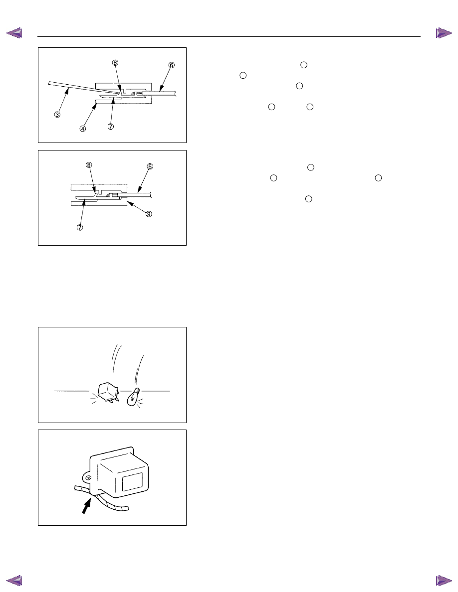
Pin Tang Lock Type
5. Insert a slender shaft
3
into the connector housing open
end
4
.
5. Push the tang lock
8
flat (toward the wire side of the
connector).
Pull the wire
6
with pin
7
free from the wire side of the
connector.
Connector Pin Insertion
5. Check that the tang lock
8
is fully up.
5. Insert the pin
7
from the connector wire side
9
.
Push the pin in until the tang lock closes firmly.
5. Gently pull on the wires
6
to make sure that connector pin
is firmly set in place.
Fuse Replacement
The replacement fuse must have the same amperage
specification as the original fuse.
Never replace a burn out fuse with a fuse of a different
amperage specification.
Doing so can result in an electrical fire or other serious circuit
damage.
Parts Handling
Be careful for parts handling and any part should not be
dropped or thrown, otherwise short circuit or disorder may
result.
Wiring Harness
5. When assembling the parts, be careful not to bite or wedge
the wiring harness.
5. All electrical connections must be kept clean and tight.
8A-8 ELECTRICAL-BODY AND CHASSIS
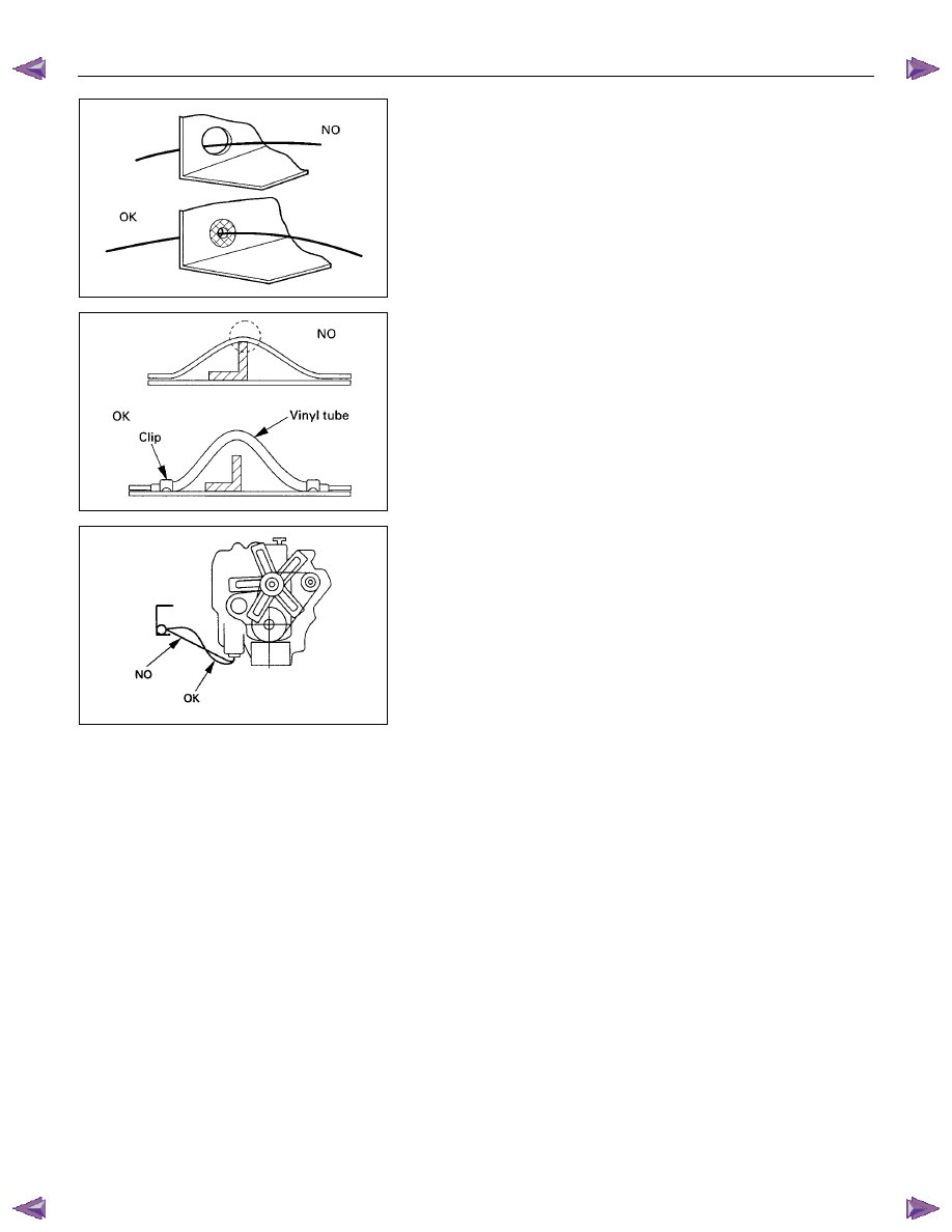
5. Use a grommet or guard tube to protect the wiring harness
from contacting a sharp edge or surface.
5. Position the wiring harness with enough clearance from the
other parts and guard the wiring harness with a vinyl tube
to avoid direct contact.
5. The wiring harness between engine and chassis should be
long enough to prevent chafing or damage due to various
vibrations.
ELECTRICAL-BODY AND CHASSIS 8A-9
SPLICING WIRE
Open the Harness
If the harness is taped, remove the tape.
To avoid wire insulation damage, use a sewing “seam ripper”
(available from sewing supply stores) to cut open the harness.
If the harness has a black plastic conduit, simply pull out the
desired wire.
Cut the wire
Begin by cutting as little wire off the harness as possible.
You may need the extra length of wire later if you decide to cut
more wire off to change the location of a splice.
You may have to adjust splice locations to make certain that
each splice is at least 1-1/2” (40 mm) away from other splices,
harness branches, or connectors.
Strip the insulation
When replacing a wire, use a wire of the same size as the
original wire.
Check the stripped wire for nicks or cut strands.
If the wire is damaged, repeat the procedure on a new section
of wire.
The two stripped wire ends should be equal in length.
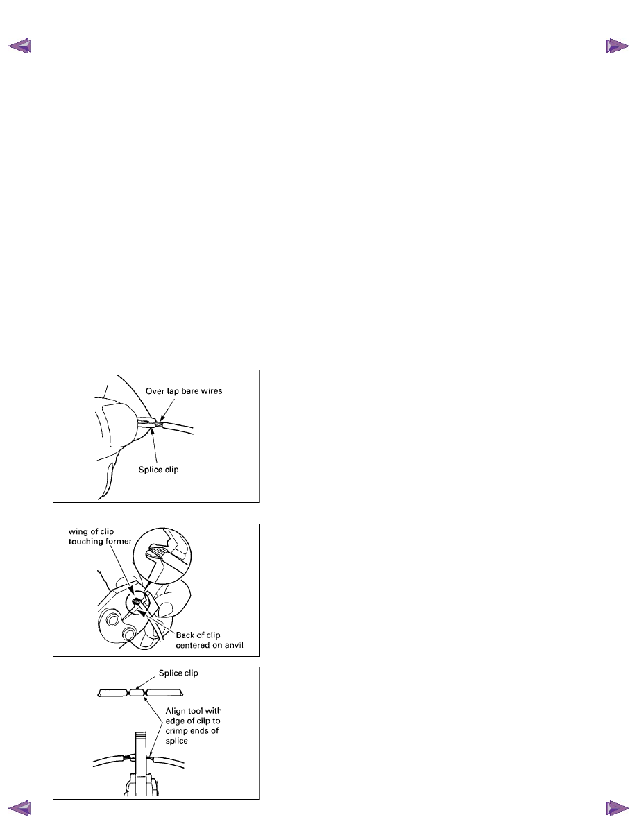
Crimp the Wires
Select the proper clip to secure the splice.
To determine the proper clip size for the wire being spliced,
follow the directions included with your clips.
Select the correct anvil on the crimper.
(On most crimpers your choice is limited to either a small or
large anvil.)
Overlap the two stripped wire ends and hold them between
your thumb and forefinger.
Then, enter the splice clip under the stripped wires and hold it
in place.
• Open the crimping tool to its full width and rest one handle
on a firm flat surface.
• Center the back of the splice clip on the proper anvil and
close the crimping tool to the point where the back of the
splice clip touches the wings of the clip.
• Make sure that the clip and wires are still in the correct
position. Then, apply pressure until the crimping tool closes.
Before crimping the ends of the clip, be sure that:
• The wires extend beyond the clip in each direction.
• No strands of wire are cut loose.
• No insulation is caught under the clip.
Crimp the splice again, once on each end.
Do not let the crimping tool extend beyond the edge of the clip
or you may damage or nick the wires.
Нет комментариевНе стесняйтесь поделиться с нами вашим ценным мнением.
Текст