Isuzu KB P190. Manual — part 225
ENGINE MECHANICAL 6A – 95
Reassembly
1. Cylinder
Head
2. Valve Spring Lower Seat
3. Valve Stem Oil Seal
1. Apply a coat of engine oil to the oil seal inner face.
2. Use an oil seal installer to install the oil seal to the
valve guide.
Oil Seal Installer: 5-8840-2033-0
4. Intake and Exhaust Valve
1. Apply a coat of engine oil to each valve stem before
installation.
2. Install the intake and exhaust valves.
3. Turn the cylinder head up to install the valve
springs.Take care not to allow the installed valves to
fall free.
5. Valve
Spring
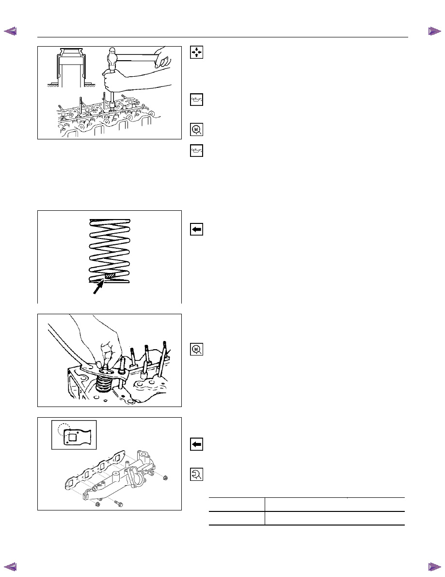
Install the valve spring with their fine pitched end (painted)
facing down.
6. Valve Spring Upper Seat
7. Split
Collar
1. Use the spring compressor to compress the valve
spring into position.
Spring Compressor: 9-8523-1423-0
2. Install the split collars to the valve stem.
3. Set the split collars by tapping around the head of the
collar with a rubber hammer.
RTW46ASH002301
8. Intake manifold gasket
9. Intake
manifold
1. Install the manifold gasket with the end having the
sharp corners facing the rear of the engine.
2. Install the intake manifold to the cylinder head.
3. Tighten the manifold bolt/nuts to the specified torque.
Manifold Bolt/Nut Torque
N·m(kg·m/lbft)
Bolt 19
(1.9/14)
Nut 24
(2.4/17)
011RW027
011LX055
014RY00039
6A – 96 ENGINE MECHANICAL
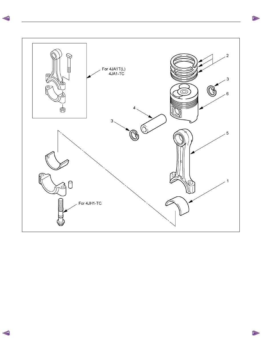
PISTON AND CONNECTING ROD
RTW46ALF000301
Reassembly Steps
1.
Piston
5.
Piston pin snap ring
2.
Connecting rod
6.
Piston ring
3.
Piston pin snap ring
7.
Connecting rod bearing
4.
Piston pin
ENGINE MECHANICAL 6A – 97
Reassembly
1. Piston
2. Connecting
Rod
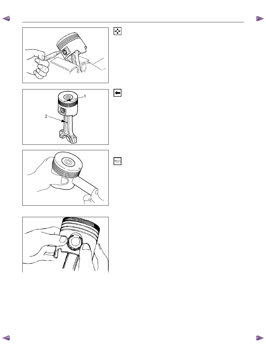
1. Clamp the connecting rod in a vise.Take care not to
damage the connecting rod.
2. Use a pair of pliers to install the piston pin snap ring to
the piston.
RTW36ASH001801
Install the piston to the connecting rod so that the piston
head front mark (1) and the connecting rod mark (2) are
facing in the same direction.
3. Piston Pin Snap Ring
RTW36ASH001901
4. Piston
Pin
1. Apply a coat of engine oil to the piston pin and the
piston pin hole.
2. Use your fingers to force the piston pin into the piston
until it makes contact with the snap ring.
5. Piston Pin Snap Ring
1. Use your fingers to force the piston pin snap ring into
the piston snap ring groove.
2. Check that the connecting rod moves smoothly on the
piston pin.
F06MV015
015R100001
6A – 98 ENGINE MECHANICAL
RTW36ASH002001
6. Piston
Ring
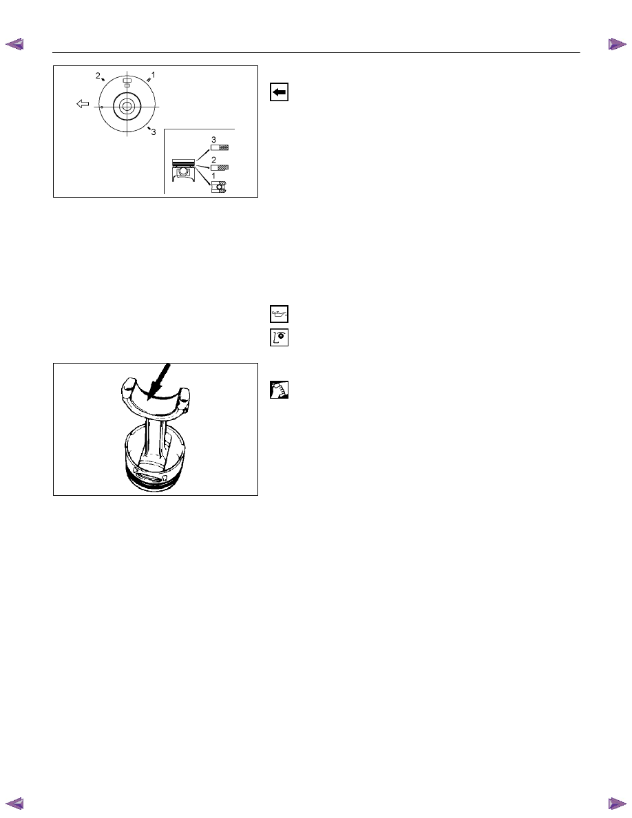
1. Use a piston ring replacer to install the three piston
rings.
Piston Ring Replacer
Install the piston rings in the order shown in the
illustration.
1. Oil
ring
2. 2nd compression ring
3. 1st compression ring
NOTE:
Install the compression rings with the stamped side
facing up.
Insert the expander coil into the oil ring groove so that
there is no gap on either side of the expander coil
before installing the oil ring.
2. Apply engine oil to the piston ring surfaces.
3. Check that the piston rings rotate smoothly in the
piston ring grooves
7. Connecting Rod Bearing
Carefully wipe any oil or other foreign material from the
connecting rod bearing back face and the connecting rod
bearing fitting surface.
015R100006
Нет комментариевНе стесняйтесь поделиться с нами вашим ценным мнением.
Текст