Isuzu KB P190. Manual — part 224
ENGINE MECHANICAL 6A – 91
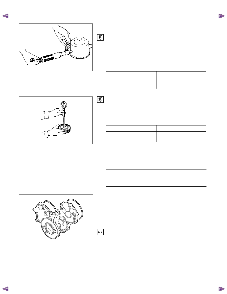
IDLER GEAR SHAFT AND IDLER GEAR
Idler Gear "A" Shaft Outside Diameter
Use a micrometer to measure the idler gear shaft outside
diameter.
If the measured value is less than the specified limit, the idler
gear shaft must be replaced.
Idler Gear "A" Shaft Outside Diameter
mm (in)
Standard
Limit
44.945-44.975
(1.7695-1.7707)
44.845 (1.755)
Idler Gear "A" Shaft inside Diameter
1. Use an inside dial indicator or an inside micrometer to
measure the idler gear inside diameter.
Idler Gear Inside Diameter mm
(in)
Standard
Limit
45.0-45.03
(1.7717-1.7718)
45.10 (1.7756)
If the clearance between the idler gear shaft outside diameter
and the idler gear inside diameter exceeds the limit, the idler
gear must be replaced.
Idler Gear Shaft and Idler Gear Clearance
mm (in)
Standard
Limit
0.025-0.085
(0.0010-0.0033)
0.200 (0.0079)
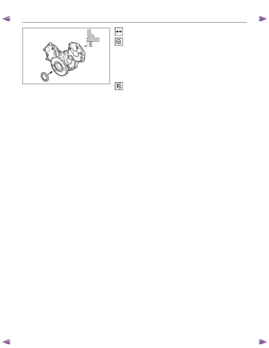
TIMING GEAR CASE COVER
Replace the crankshaft front oil seal if it is excessively worn or
damaged.
Crankshaft Front Oil Seal Replacement
Oil Seal Removal
Use a plastic hammer and a screwdriver to tap around the oil
seal to free it from the gear case cover.
Take care not to damage the oil seal lip surfaces.
020RY00025
014LX022
020R300004
6A – 92 ENGINE MECHANICAL
Oil Seal Installation
Use the special tool to install the front oil seal.
Front Oil Seal Installer: 5-8840-2361-0
1. With the oil seal attached to the sleeve, insert it into the
front end section of the crankshaft.
2. With the oil seal end section attached securely to the
crankshaft, tighten up the center bolt until the sleeve hits
the front end reference plane of the crankshaft securely.
3. Remove the sleeve.
4. With the seal pressed in, check the dimension of the oil
seal section.
Standard Dimension = 1.0
±
0.03mm
NOTE:
Install the oil seal after assembling the timing pulley
housing. The oil seal lip section is applied with oil.
Take notice of the press-in direction of the oil seal.
020R300005
ENGINE MECHANICAL 6A – 93
REASSEMBLY
INTERNAL PARTS
MINOR COMPONENT
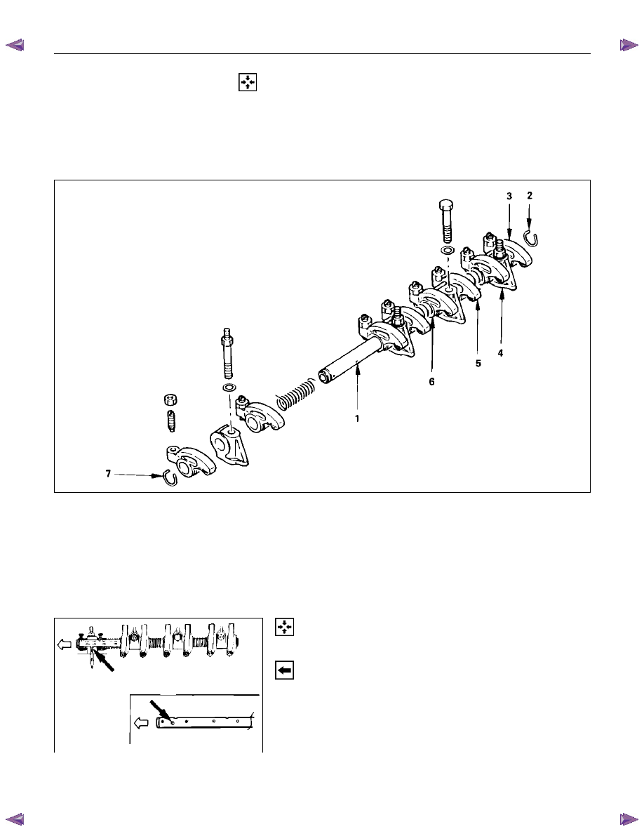
ROCKER ARM SHAFT AND ROCKER ARM
020RY00029
Reassembly Steps
1.
Rocker arm shaft
5.
Rocker arm
2.
Rocker arm shaft snap ring
6.
Rocker arm shaft spring
3.
Rocker arm
7.
Rocker arm shaft snap ring
4.
Rocker arm shaft bracket
Reassembly
1. Rocker Arm Shaft
1. Position the rocker arm shaft with the large oil hole (4
φ) facing the front of the engine.
2. Install the rocker arm shaft together with the rocker
arm, the rocker arm shaft bracket, and the spring.
2. Rocker Arm Shaft Snap Ring
3. Rocker
Arm
4. Rocker Arm Shaft Bracket
5. Rocker
Arm
6. Rocker Arm Shaft Spring
7. Rocker Arm Shaft Snap Ring
014RY00037

6A – 94 ENGINE MECHANICAL
CYLINDER HEAD
RTW46ALF001301
Reassembly Steps
1.
Cylinder head
6.
Valve spring upper seat
2.
Valve spring lower seat
7.
Split collar
3.
Valve stem oil seal
8.
Intake manifold gasket
4.
Intake and exhaust valve
9.
Intake manifold
5.
Valve spring
Нет комментариевНе стесняйтесь поделиться с нами вашим ценным мнением.
Текст