Isuzu KB P190. Manual — part 74
POWER-ASSISTED STEERING SYSTEM 3B-35
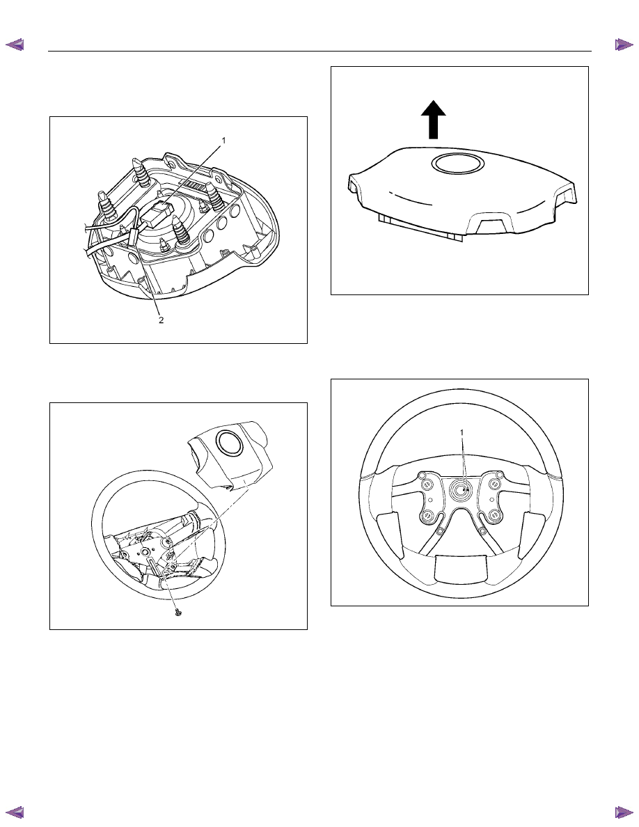
11. Disconnect the SRS air bag connector (1) and horn
lead connector (2) located behind the air bag
assembly and remove the air bag assembly (with
SRS air bag).
RTW73BSH001101
12. Remove the horn pad and the horn leads at the
center of the wheel (without SRS air bag).
NOTE: It should be removed first from the bottom
spokes.
RTW73BSH000601
WARNING: THE INFLATOR MODULE SHOULD
ALWAYS BE CARRIED WITH THE COVER AWAY
FROM YOUR BODY AND SHOULD ALWAYS BE
LAID ON A FLAT SURFACE WITH THE COVER SIDE
UP. THIS IS NECESSARY BECAUSE A FREE SPACE
IS PROVIDED TO ALLOW THE AIR CUSHION TO
EXPAND IN THE UNLIKELY EVENT OF
ACCIDENTAL DEPLOYMENT. OTHERWISE,
PERSONAL INJURY MAY RESULT (with SRS air
bag).
430R300007
13. Apply a setting mark (1) across the steering wheel
and shaft so parts can be reassembled in their
original position. Move the front wheels to the
straight ahead position, then use steering wheel
remover 5-8521-0016-0 (2) to remove the steering
wheel.
RTW73BSH000501
CAUTION: Never apply force to the steering wheel in
the direction of the shaft by using a hammer or
other impact tools in an attempt to remove the
steering wheel. The steering shaft is designed as an
energy absorbing unit.
3B-36 POWER-ASSISTED STEERING SYSTEM
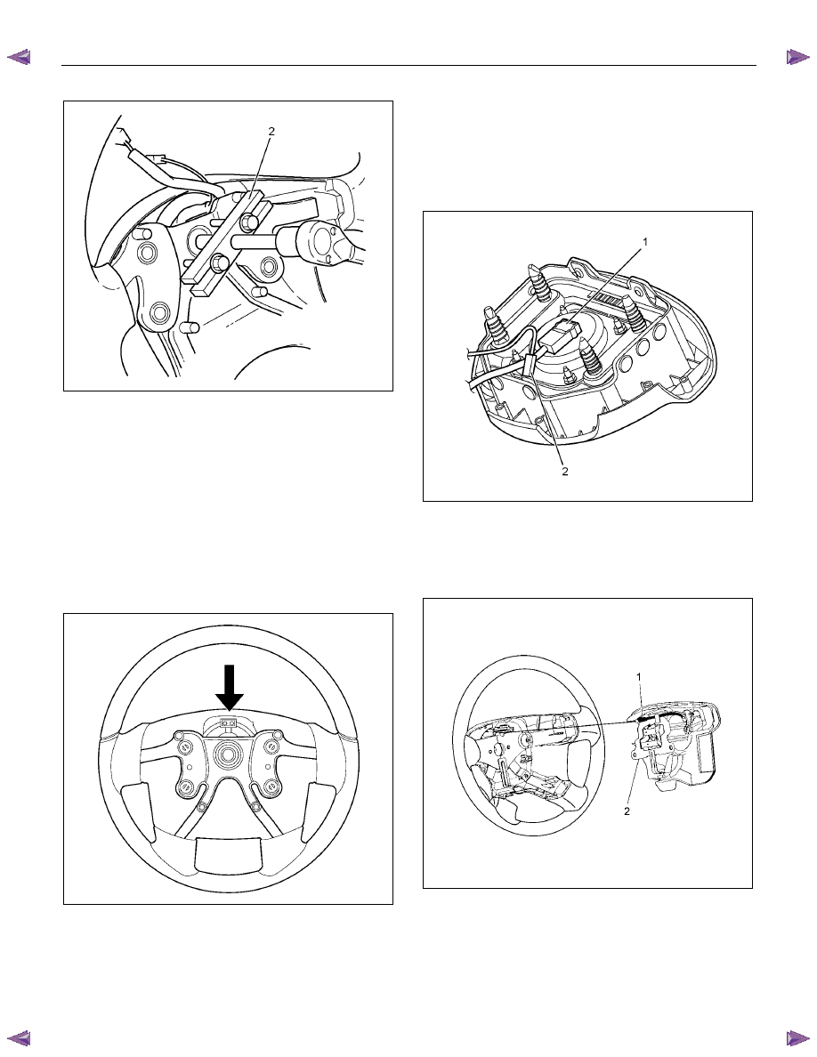
RTW73BSH001301
14. Remove steering column cover.
15. Disconnect the wiring harness connectors located
under the steering column then remove combination
switch and SRS coil assembly.
Installation
1. Align the setting marks made when removing, then
install steering wheel.
Refer to the adjustment method in case a mark has
not been applied in this section.
NOTE: Confirm SRS and horn harness connector is
fixed by the steering wheel.
RTW73BSH000701
CAUTION: Never apply force to the steering wheel in
the direction of the shaft by using a hammer or
other impact tools in an attempt to remove the
steering wheel. The steering shaft is designed as an
energy absorbing unit.
2. Tighten the steering wheel fixing nut to the specified
torque.
Torque: 35 N
⋅⋅⋅⋅m (3.6 kgf⋅⋅⋅⋅m/26 lb⋅⋅⋅⋅ft)
3. Support the inflator module and carefully connect the
SRS connector (1) and horn lead (2) (with SRS air
bag).
RTW73BSH001101
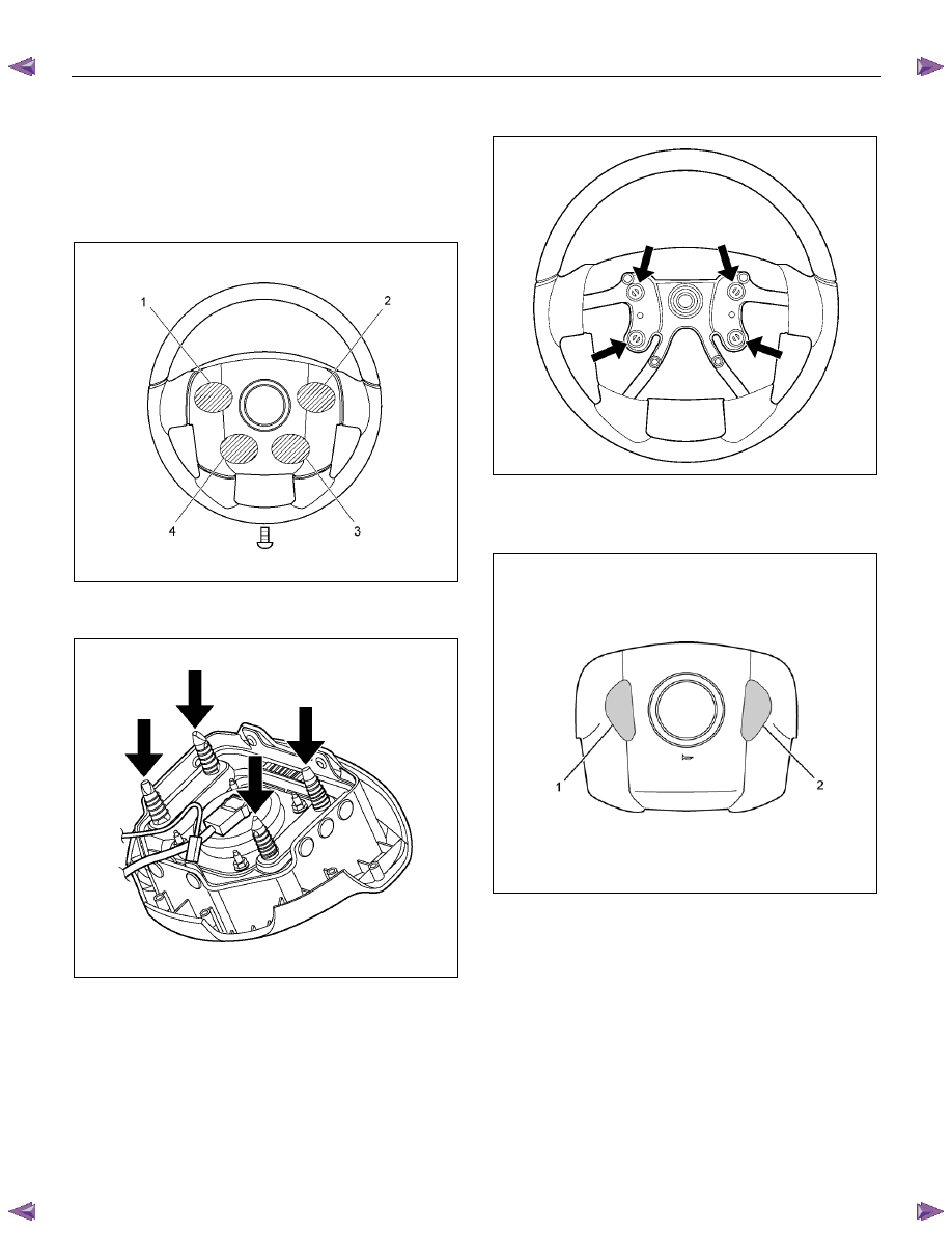
4. Connect the horn leads at center of wheel (without
SRS air bag).
NOTE: The horn leads (1) are passed along the top of
the bracket (2).
(Plastic type steering wheel only)
RTW73BSH000801
POWER-ASSISTED STEERING SYSTEM 3B-37
5. Push the horn pad at areas 1-4.
Tighten the horn pad fixing screw to the specifed
torque (without SRS air bag)
Torque: 3 N
⋅⋅⋅⋅m (0.3 kgf⋅⋅⋅⋅m/26 lb⋅⋅⋅⋅in)
NOTE: A horn pad should not be struk during
attachment.
RTW73BSH000201
6. Align each snap stud of driver air bag to the holes on
steering wheel. (with SRS air bag)
RTW73BSH001201
RTW73BSH000401
7. Push the SRS air at bag at area-1 (1) and area-2 (2).
At that time confirm the audible noise of each stud.
(with SRS air bag)
RTW73BSH000301
8. Enable the SRS (Refer to "Enabling the SRS" in this
section) (with SRS air bag).
9. Connect the SRS connector (with SRS air bag).
10. Connect the battery "-" terminal cable (with SRS air
bag).
11.
Turn the ignition switch to "ON" while watching
warning light and check - the light should flash 7
times and then go off. If lamp does not operate
correctly, refer to Restraints section.
3B-38 POWER-ASSISTED STEERING SYSTEM
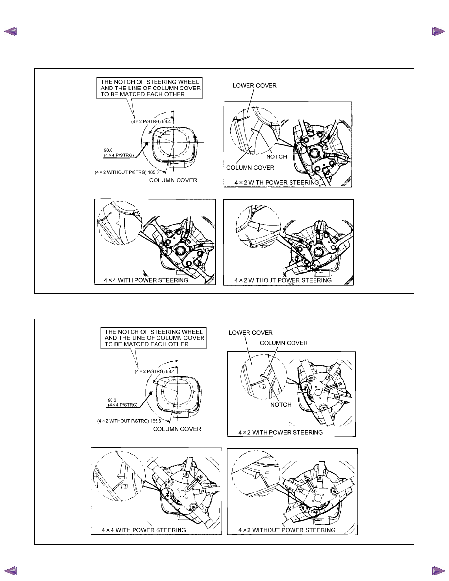
The adjustment method in case a mark has not been applied
with SRS air bag
RTW63BMF000201
without SRS air bag
RTW63BMF000301
Нет комментариевНе стесняйтесь поделиться с нами вашим ценным мнением.
Текст