Isuzu KB P190. Manual — part 75
POWER-ASSISTED STEERING SYSTEM 3B-39
Combination Switch
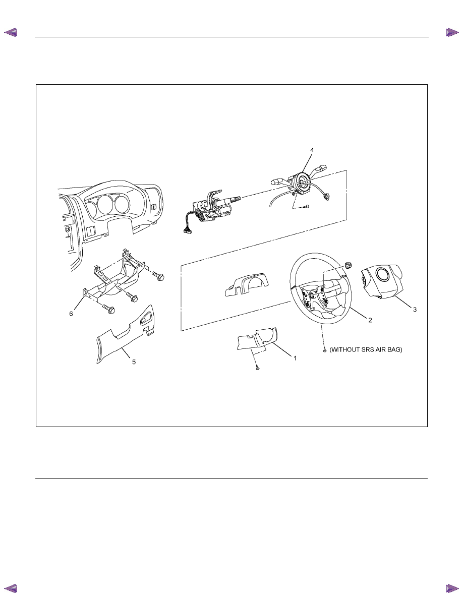
Combination Switch and Associated Parts
RTW73BLF000201
Legend
(1) Steering Column Cover
(2) Steering Wheel
(3) Inflator Module or Horn Pad
(4) Combination Switch and SRS Coil Assembly
(5) Instrument Panel Lower Cover
(6) Driver Knee Bolster (reinforcement)
Removal
1. Turn the steering wheel so that the vehicle's wheels
are pointing straight ahead.
2. Turn the ignition switch to "LOCK".
3. Disconnect the battery "-" terminal cable, and wait at
least 5 minutes (with SRS air bag).
4. Disconnect the yellow 2-way SRS connector located
under the steering column (with SRS air bag).
CAUTION: The wheels of the vehicle must be
straight ahead and the steering column in the
"LOCK" position before disconnecting the steering
wheel. Failure to do so will cause the coil assembly
to lose its centering which will cause damage to the
coil assembly. (with SRS air bag)
5. Remove the engine hood opening lever, then
remove instrument panel lower cover.
6. Remove the driver knee bolster (reinforcement).
3B-40 POWER-ASSISTED STEERING SYSTEM
7. Disable the SRS (Refer to "Disabling the SRS" in
this section) (with SRS air bag).
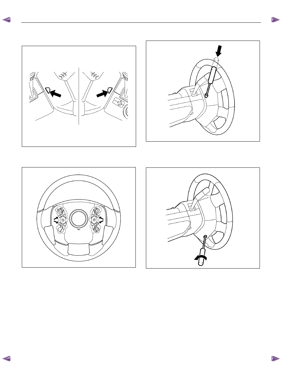
8. Check the holes on both sides of the steering cover.
060R300025
9. Check the position of the pins in their holes. Push
the pin in the direction of the arrow (with SRS air
bag).
RTW73BSH000101
10. Push the four pins with a φ 5~6 mm (0.20~0.24 in)
bar (with SRS air bag).
060R300031
11. Cancel the lock to release the four pins (with SRS
air bag).
12. Loosen the horn pad fixing screw at the rear of the
steering wheel (without SRS air bag).
430R300009
POWER-ASSISTED STEERING SYSTEM 3B-41
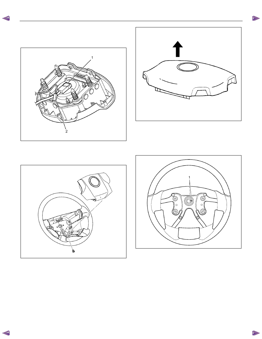
13. Disconnect the SRS air bag connector (1) and horn
lead connector (2) located behind the air bag
assembly and remove the air bag assembly (with
SRS air bag).
RTW73BSH001101
14. Remove the horn pad and the horn leads at the
center of the wheel (without SRS air bag).
NOTE: It should be removed first from the bottom
spokes.
RTW73BSH000601
WARNING: THE INFLATOR MODULE SHOULD
ALWAYS BE CARRIED WITH THE COVER AWAY
FROM YOUR BODY AND SHOULD ALWAYS BE
LAID ON A FLAT SURFACE WITH THE COVER SIDE
UP. THIS IS NECESSARY BECAUSE A FREE SPACE
IS PROVIDED TO ALLOW THE AIR CUSHION TO
EXPAND IN THE UNLIKELY EVENT OF
ACCIDENTAL DEPLOYMENT. OTHERWISE,
PERSONAL INJURY MAY RESULT (with SRS air
bag).
430R300007
15. Apply a setting mark (1) across the steering wheel
and shaft so parts can be reassembled in their
original position. Move the front wheels to the
straight ahead position, then use steering wheel
remover 5-8521-0016-0 (2) to remove the steering
wheel.
RTW73BSH000501
CAUTION: Never apply force to the steering wheel in
the direction of the shaft by using a hammer or
other impact tools in an attempt to remove the
steering wheel. The steering shaft is designed as an
energy absorbing unit.
3B-42 POWER-ASSISTED STEERING SYSTEM
CAUTION: When turning the SRS coil fully
counterclockwise, stop turning if resistance is felt.
Further forced turning may damage the cable in the
SRS coil (with SRS air bag).
826RW014
Legend
(1) Neutral mark
RTW73BSH001301
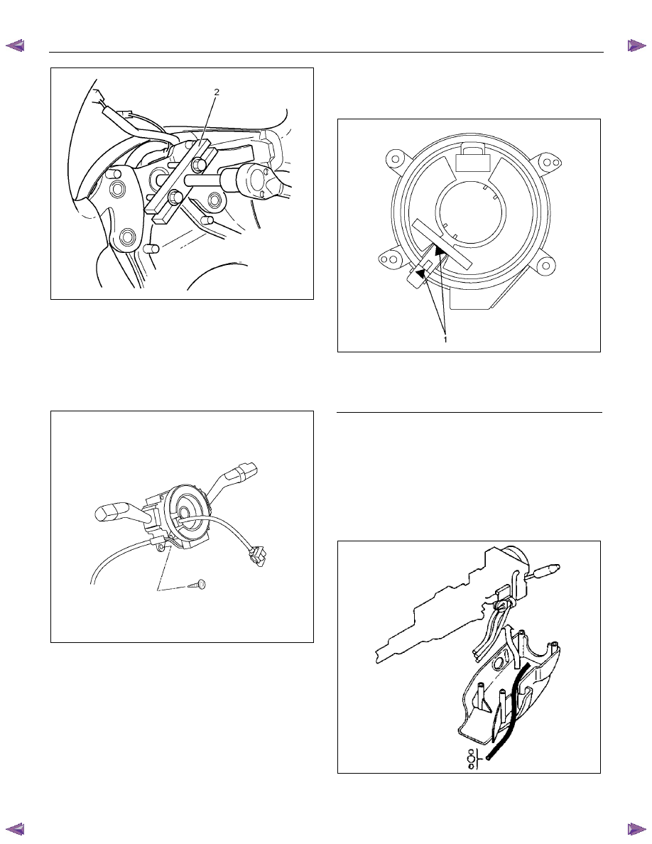
16. Remove steering column cover.
17. Disconnect the wiring harness connectors located
under the steering column then remove combination
switch and SRS coil assembly (with SRS air bag).
NOTE: The SRS coil is a part of the combination switch
assembly, which cannot be replaced separately.
Therefore, be sure not to remove the SRS coil from the
combination switch assembly (with SRS air bag).
RTW73BSH001001
Installation
1. Install the combination switch assembly with SRS
coil (with SRS air bag).
2. Turn the SRS coil fully counterclockwise, return
about 3 turns and align the neutral mark (with SRS
air bag).
3. Connect the wiring harness connectors located at
the base of steering column.
4. Install the air conditioning lower duct.
5. Install the steering column cover.
CAUTION: When installing the steering column
cover, be sure to wire (through each harness) as
illustrated so that the harness starter switch,
combination switch and SRS coil will not catch
wiring (with SRS air bag).
825RS048
Нет комментариевНе стесняйтесь поделиться с нами вашим ценным мнением.
Текст