Isuzu KB P190. Manual — part 915
Battery
Page 6D1-3–20
6
Torque Wrench Specifications
Battery Hold-Down Bolts . . . . . . . . . . . . . . . . 8.0 – 10.0 Nm
Battery Terminal Nut. . . . . . . . . . . . . . . . . .. 2.0 – 5.0 Nm
Battery
Page 6D1-3–21
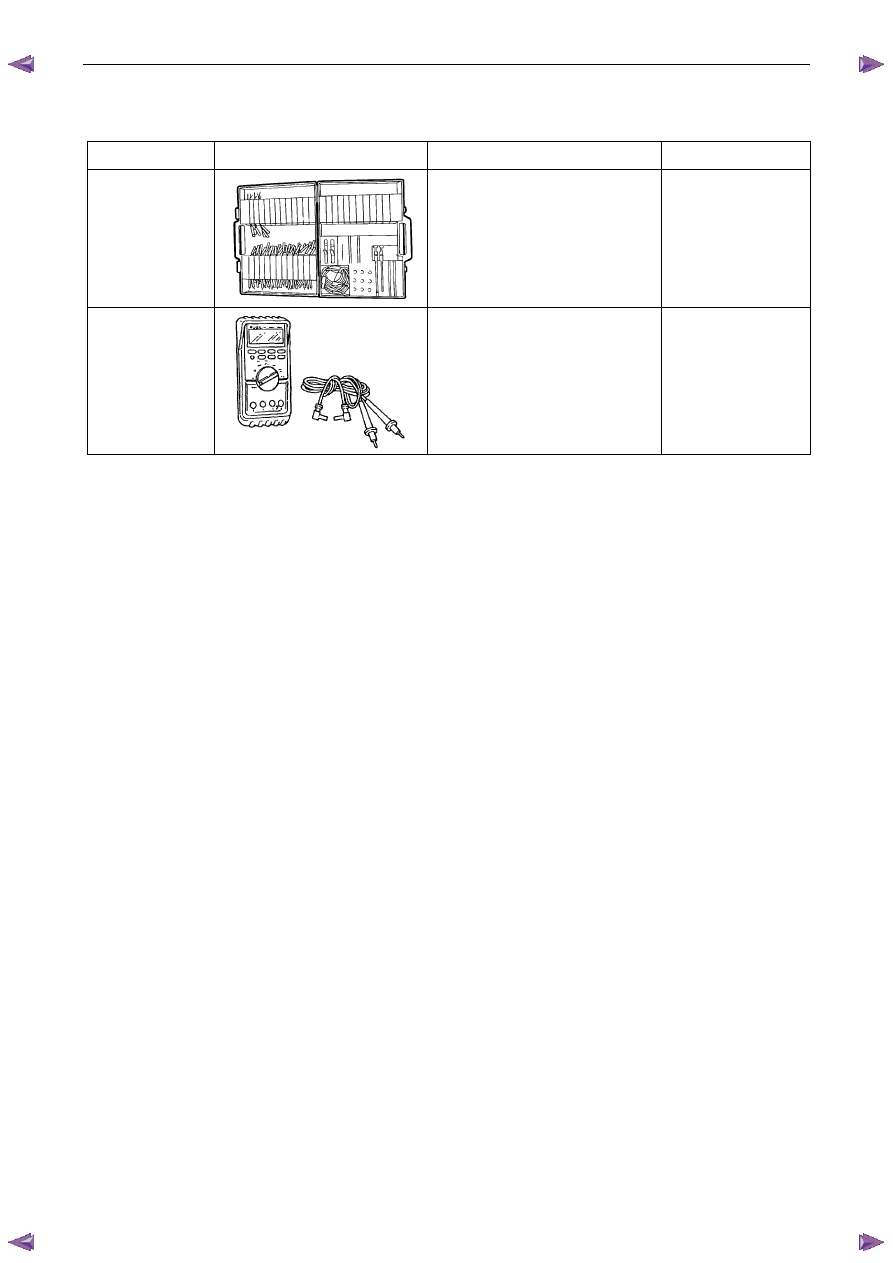
7 Special
Tools
Tool
Number Illustration
Description Tool
Classification
KM609
Connector Test Adaptor Kit
Used when carrying out electrical
diagnostic circuit checks.
Previously released.
Desirable
J39200
Digital Multimeter
Must have at least 10 M
Ω input
impedance and be capable of reading
frequencies.
Previously released.
Available

Powertrain Interface Module – V6
Page 6E1–1
6E1
Powertrain Interface Module – V6
A T T E N T I O N
Before performing any service operation or other procedure described in this Section, refer to 1.2 Warning
Caution and Notes for correct workshop practices with regard to safety and / or property damage.
1
General Information . . . . . . . . . . . . . . . . . . . . . . . . . . . . . . . ...6
1.1
General Description. . . . . . . . . . . . . . . . . . . . . . . . . . . . . . . . . . . ... 6
Serial Data Communication . . . . . . . . . . . . . . . . . . . . . . . . . . . . . . . . .. 6
Serial Data Layout. . . . . . . . . . . . . . . . . . . . . . . . . . . . . . . . . . . . .. 8
1.2
Warning Caution and Notes . . . . . . . . . . . . . . . . . . . . . . . . . . . . . . . . .. 8
Definition of WARNING, CAUTION and NOTE Statements. . . . . . . . . . . . . . . . . . . . . 8
2
Component Location. . . . . . . . . . . . . . . . . . . . . . . . . . . . . . . 10
2.1
Engine Compartment. . . . . . . . . . . . . . . . . . . . . . . . . . . . . . . . . . ... 10
2.2
Interior. . . . . . . . . . . . . . . . . . . . . . . . . . . . . . . . . . . . . . . . ... 11
3
Component Description and Operation . . . . . . . . . . . . . . . . . . . . . . . .12
3.1
Powertrain Interface Module . . . . . . . . . . . . . . . . . . . . . . . . . . . . . . . ... 12
3.2
Powertrain Interface Module Gateway Components . . . . . . . . . . . . . . . . . . . . . . 13
Engine Control Module. . . . . . . . . . . . . . . . . . . . . . . . . . . . . . . . . . 13
Immobiliser Control Unit . . . . . . . . . . . . . . . . . . . . . . . . . . . . . . . . . . 13
Automatic Transmission Control Module . . . . . . . . . . . . . . . . . . . . . . . . . . .. 13
3.3
Powertrain Interface Module Direct Input Switches. . . . . . . . . . . . . . . . . . . . . . .. 14
Cruise Control Switch. . . . . . . . . . . . . . . . . . . . . . . . . . . . . . . . . . .. 14
Power Mode Switch – Automatic Transmission. . . . . . . . . . . . . . . . . . . . . . . . 14
Start Switch – Automatic Transmission . . . . . . . . . . . . . . . . . . . . . . . . . ... 14
4
Diagnostics . . . . . . . . . . . . . . . . . . . . . . . . . . . . . . . . . . ...15
4.1
Diagnostic General Descriptions. . . . . . . . . . . . . . . . . . . . . . . . . . . . . . 15
Diagnostic Trouble Code (DTC) Tables. . . . . . . . . . . . . . . . . . . . . . . . . . . .. 15
Diagnostic Trouble Codes (DTCs) . . . . . . . . . . . . . . . . . . . . . . . . . . . . . .. 15
Tech 2 PIM Diagnostic Tests. . . . . . . . . . . . . . . . . . . . . . . . . . . . . . . ... 16
5
GM LAN Serial Communication Circuit. . . . . . . . . . . . . . . . . . . . . . . ..17
6
Wiring Diagram and Connector Chart . . . . . . . . . . . . . . . . . . . . . . . . 18
6.1
Wiring Diagrams . . . . . . . . . . . . . . . . . . . . . . . . . . . . . . . . . . . . .. 18
6.2
Connector Chart. . . . . . . . . . . . . . . . . . . . . . . . . . . . . . . . . . . . ... 20
6.3
Connector Information . . . . . . . . . . . . . . . . . . . . . . . . . . . . . . . . . . 21
PIM Connector Pin Specifications. . . . . . . . . . . . . . . . . . . . . . . . . . . . . .. 21
7
Diagnostics Starting Point . . . . . . . . . . . . . . . . . . . . . . . . . . . . ..24
7.1
Diagnostic Requirements, Precautions and Preliminary Checks. . . . . . . . . . . . . . . . . 24
Basic Knowledge Required. . . . . . . . . . . . . . . . . . . . . . . . . . . . . . . . . 24
Basic Diagnostic Tools Required . . . . . . . . . . . . . . . . . . . . . . . . . . . . . ... 24
Diagnostic Precautions . . . . . . . . . . . . . . . . . . . . . . . . . . . . . . . . . ... 24
Preliminary Checks. . . . . . . . . . . . . . . . . . . . . . . . . . . . . . . . . . . .. 25
7.2
Diagnostic System Check . . . . . . . . . . . . . . . . . . . . . . . . . . . . . . . . ... 25
7.3
Powertrain Interface Module – Module Communication Check Failure Diagnostic Table. . . . . . . . 27
Powertrain Interface Module – V6
Page 6E1–2
8
Intermittent Fault Conditions . . . . . . . . . . . . . . . . . . . . . . . . . . . ..29
8.1
Intermittent Conditions Diagnostic Table . . . . . . . . . . . . . . . . . . . . . . . . . . .. 29
Description . . . . . . . . . . . . . . . . . . . . . . . . . . . . . . . . . . . . . . ... 29
Diagnostic Table . . . . . . . . . . . . . . . . . . . . . . . . . . . . . . . . . . . . .. 29
9
DTC Tables. . . . . . . . . . . . . . . . . . . . . . . . . . . . . . . . . . . 31
9.1
DTC C0550 – PIM Internal Fault . . . . . . . . . . . . . . . . . . . . . . . . . . . . . . .. 31
DTC Description. . . . . . . . . . . . . . . . . . . . . . . . . . . . . . . . . . . . ... 31
Circuit Description. . . . . . . . . . . . . . . . . . . . . . . . . . . . . . . . . . . ... 31
Additional Information. . . . . . . . . . . . . . . . . . . . . . . . . . . . . . . . . . . 31
Conditions for Running the DTC . . . . . . . . . . . . . . . . . . . . . . . . . . . . . . 31
Conditions for Setting the DTC. . . . . . . . . . . . . . . . . . . . . . . . . . . . . . ... 31
Action Taken When the DTC Sets . . . . . . . . . . . . . . . . . . . . . . . . . . . . . .. 31
Conditions for Clearing the DTC . . . . . . . . . . . . . . . . . . . . . . . . . . . . . . 31
Test Description. . . . . . . . . . . . . . . . . . . . . . . . . . . . . . . . . . . . ... 31
DTC C0550 Diagnostic Table . . . . . . . . . . . . . . . . . . . . . . . . . . . . . . . .. 32
9.2
DTC U2100 – No Communication With CAN Bus (High Speed) . . . . . . . . . . . . . . . . . ... 32
DTC Description. . . . . . . . . . . . . . . . . . . . . . . . . . . . . . . . . . . . ... 32
Circuit Description. . . . . . . . . . . . . . . . . . . . . . . . . . . . . . . . . . . ... 32
Additional Information. . . . . . . . . . . . . . . . . . . . . . . . . . . . . . . . . . . 32
Conditions for Running the DTC . . . . . . . . . . . . . . . . . . . . . . . . . . . . . . 33
Conditions for Setting the DTC. . . . . . . . . . . . . . . . . . . . . . . . . . . . . . ... 33
Action Taken When the DTC Sets . . . . . . . . . . . . . . . . . . . . . . . . . . . . . .. 33
Conditions for Clearing the DTC . . . . . . . . . . . . . . . . . . . . . . . . . . . . . . 33
Test Description. . . . . . . . . . . . . . . . . . . . . . . . . . . . . . . . . . . . ... 33
DTC U2100 Diagnostic Table . . . . . . . . . . . . . . . . . . . . . . . . . . . . . . . .. 33
9.3
DTC U2105 – CAN Bus No Communication With Engine Control Module . . . . . . . . . . . . . .. 35
DTC Description. . . . . . . . . . . . . . . . . . . . . . . . . . . . . . . . . . . . ... 35
Circuit Description. . . . . . . . . . . . . . . . . . . . . . . . . . . . . . . . . . . ... 35
Additional Information. . . . . . . . . . . . . . . . . . . . . . . . . . . . . . . . . . . 35
Conditions for Running the DTC . . . . . . . . . . . . . . . . . . . . . . . . . . . . . . 35
Conditions for Setting the DTC. . . . . . . . . . . . . . . . . . . . . . . . . . . . . . ... 35
Action Taken When the DTC Sets . . . . . . . . . . . . . . . . . . . . . . . . . . . . . .. 35
Conditions for Clearing the DTC . . . . . . . . . . . . . . . . . . . . . . . . . . . . . . 36
Test Description. . . . . . . . . . . . . . . . . . . . . . . . . . . . . . . . . . . . ... 36
DTC U2105 Diagnostic Table . . . . . . . . . . . . . . . . . . . . . . . . . . . . . . . .. 36
9.4
DTC U2106 – CAN Bus No Communication With Transmission Control Module. . . . . . . . . . ... 38
DTC Description. . . . . . . . . . . . . . . . . . . . . . . . . . . . . . . . . . . . ... 38
Circuit Description. . . . . . . . . . . . . . . . . . . . . . . . . . . . . . . . . . . ... 38
Additional Information. . . . . . . . . . . . . . . . . . . . . . . . . . . . . . . . . . . 38
Conditions for Running the DTC . . . . . . . . . . . . . . . . . . . . . . . . . . . . . . 38
Conditions for Setting the DTC. . . . . . . . . . . . . . . . . . . . . . . . . . . . . . ... 38
Action Taken When the DTC Sets . . . . . . . . . . . . . . . . . . . . . . . . . . . . . .. 38
Conditions for Clearing the DTC . . . . . . . . . . . . . . . . . . . . . . . . . . . . . . 38
Test Description. . . . . . . . . . . . . . . . . . . . . . . . . . . . . . . . . . . . ... 38
DTC U2106 Diagnostic Table . . . . . . . . . . . . . . . . . . . . . . . . . . . . . . . .. 39
9.5
DTC B0565 – Coolant Temperature Gauge Circuit High Current. . . . . . . . . . . . . . . . . . 40
9.6
DTC B0575 – Fuel Gauge Circuit High Current . . . . . . . . . . . . . . . . . . . . . . . . . 40
9.7
DTC B3598 – Cruise Control Cancel Signal Malfunction. . . . . . . . . . . . . . . . . . . . .. 41
DTC Description. . . . . . . . . . . . . . . . . . . . . . . . . . . . . . . . . . . . ... 41
Circuit Description. . . . . . . . . . . . . . . . . . . . . . . . . . . . . . . . . . . ... 41
Additional Information. . . . . . . . . . . . . . . . . . . . . . . . . . . . . . . . . . . 41
Conditions for Running the DTC . . . . . . . . . . . . . . . . . . . . . . . . . . . . . . 41
Conditions for Setting the DTC. . . . . . . . . . . . . . . . . . . . . . . . . . . . . . ... 41
Action Taken When the DTC Sets . . . . . . . . . . . . . . . . . . . . . . . . . . . . . .. 41
Conditions for Clearing the DTC . . . . . . . . . . . . . . . . . . . . . . . . . . . . . . 41
Test Description. . . . . . . . . . . . . . . . . . . . . . . . . . . . . . . . . . . . ... 42
DTC B3628 Diagnostic Table . . . . . . . . . . . . . . . . . . . . . . . . . . . . . . . .. 42
9.8
DTC B3627 – Cruise Control Resume Signal Malfunction. . . . . . . . . . . . . . . . . . . . 43
Нет комментариевНе стесняйтесь поделиться с нами вашим ценным мнением.
Текст