Isuzu KB P190. Manual — part 914

Battery
Page 6D1-3–16
N O T E
Charging a battery at higher current rates can
significantly reduce the life of the battery.
Charge Rate
Initial Current
Maximum Time
Required
Slow charge
4 A
24 hours
Fast charge
35 A
2 hours
6
After a few minutes, check the colour and specific gravity of the electrolyte. Refer to 3.3
Hydrometer Test.
7
Monitor the electrolyte temperature while the battery is charging. If the electrolyte temperature reaches 55
°C:
a
switch the charging current off,
b
allow the battery to cool,
c
reduce the charging current, and
d
restart charging the battery.
N O T E
For the best results, charge the battery with the
electrolyte and plates at room temperature. An
extremely cold battery may not appear to accept
current for several hours after starting the battery
charger. If the battery does not appear to accept
charge after several hours replace the battery.
8
For slow charging check the voltage and specific gravity each hour or more regularly for fast charging. Stop the
charging when there is no change in voltage or electrolyte specific gravity over three checks.
9
If the battery was fast charged connect the battery to a slow-charger for a few hours to bring the battery to the fully
charged condition. Ensure the last few hours of charge do not exceed 1 A.
10
Tighten the filler caps. Ensure they are secure.
11
Install the battery in the vehicle. Refer to 4.1
Battery.
4.3
Emergency Jump Starting Procedure
Safety Precautions
•
Read and obey the general safety precautions for working with batteries, refer to 2 Safety Precautions.
•
Do not allow the vehicles to touch each other during the jump starting procedure.
•
Ensure the assisting vehicle battery has the same voltage rating and connects negative to ground. If this is not the
case, serious injury and damage to electrical equipment can result.
•
Do not push or tow the vehicle to start it. Damage can result when unburnt fuel reaches the catalytic converter and
ignites.
•
Do not start the vehicle using a fast charger.
•
When using jumper leads, treat both the booster battery and the discharged battery with care.
•
Do not allow sparks, flame or smoking near the battery.
•
Ensure that metal tools or jumper cables do not simultaneously contact the battery positive terminal and any other
metal part of the vehicle.
Jump Starting Procedure
1
Position the assisting vehicle so the batteries of both vehicles are close together, refer to Figure 6D1-3 – 10.
2
Apply the park brake on both vehicles.
3
Ensure that P (park) is selected for automatic transmission and N (neutral) is selected for manual transmissions.
Battery
Page 6D1-3–17
4
Turn off the ignition, lights and all other electrical loads.
5
Check the battery filler caps on both batteries are tight.
6
Place a wet cloth over the battery filler caps of each battery.
7
Attach one end of the red jumper cable to the positive terminal of the booster battery.
8
Attach the other end of the same cable to the positive terminal of the discharged battery.
9
Attach one end of the black jumper cable to the negative terminal of the booster battery.
10
Attach the other end to a solid stationary, metallic point on the engine of the disabled vehicle.
N O T E
Do not connect this end directly to the negative
post of the discharged battery.
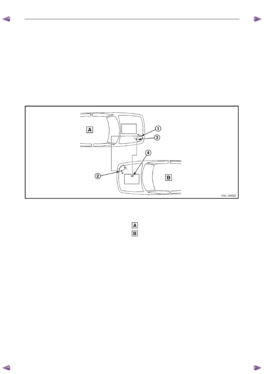
Figure 6D1-3 – 10
Legend
Order of hook-up:
1
Booster vehicle, positive terminal
2
Disabled vehicle, positive terminal
3
Booster vehicle, negative terminal
4
Disabled vehicle, engine ground point
Booster
vehicle
Disabled
vehicle
11
Ensure the jumper cables are not on or near drive pulleys, cooling fans or other points that will move when the
engine is started.
12
Start the engine in the booster vehicle and run the engine at a moderate speed for a few minutes.
13
Start the engine in the disabled vehicle.
N O T E
If the engine in the disabled vehicle does not start
within 30 seconds, stop cranking the engine and
fix the cause. Refer to 3
Diagnosis.
14
When the engine starts, allow both engines to idle for approximately seven minutes. This allows the voltage levels
in both vehicles to balance.
15
Leave the vehicles running and remove the jumper cables in the reverse sequence to attaching them. When
removing each clamp, take care to ensure that it does not touch any other metal.
16
Discard the wet cloths covering the battery filler caps of both batteries.
Battery
Page 6D1-3–18
4.4
Dry Charged Batteries
Storage
Dry charged batteries are fully charged when manufactured and contain no electrolyte until activated. The dry charged
can be stored indefinitely with no servicing until activated.
Activation
1
Remove the battery filler caps.
2
Add 1.265 specific gravity electrolyte to each cell to the correct level.
3
Wait several minutes.
4
Check the electrolyte level and add more electrolyte (not water) as required. After a dry charged battery is activated,
it becomes a wet battery.
Post Activation Tests
Although a dry charged battery can be put into service immediately after activation, the following tests are recommended:
1
Check the voltage of the battery after adding the electrolyte.
2
If the reading is less than 10 V, replace the battery.
3
Check the specific gravity of the electrolyte in each cell, refer to 3.3
Hydrometer Test.
4
If any reading shows more than a 0.030 drop from the initial electrolyte reading, slow-charge the battery before use.
Refer to 4.2 Battery Charge.
5
Check the cells for violent gassing. If violent gassing is detected evenly across all cells, slow-charge the battery
before use. If violent gassing is not even across all cells, replace the battery.
Battery
Page 6D1-3–19
5 Specifications
Rated Voltage . . . . . . . . . . . . . . . . . . . . . . . . . . . . ... 12 V
Cold Cranking Amps. . . . . . . . . . . . . . . . . . . . . . 430 A minimum
Reserve Capacity . . . . . . . . . . . . . . . . . . . . . 85 minutes minimum
20 Hour Discharge. . . . . . . . . . . . . . . . . . . . ...55 A / hour minimum
5 Second Voltage @ 25
° C. . . . . . . . . . . . . . . . . 150 A 10.4 + / – 0.2 V
. . . . . . . . . . . . . . . . . . . . . . . . . . . . . 400 A 8.4 + / – 0.2 V
Number of Plates (per cell) . . . . . . . . . . . . . . . . . . . . . . . . ...11
N O T E
Specified ratings when tested in accordance with
Australian Standard AS 2149-1990
Нет комментариевНе стесняйтесь поделиться с нами вашим ценным мнением.
Текст