Isuzu KB P190. Manual — part 1020

7A2-114 TRANSMISSION CONTROL SYSTEM (AW30–40LE)
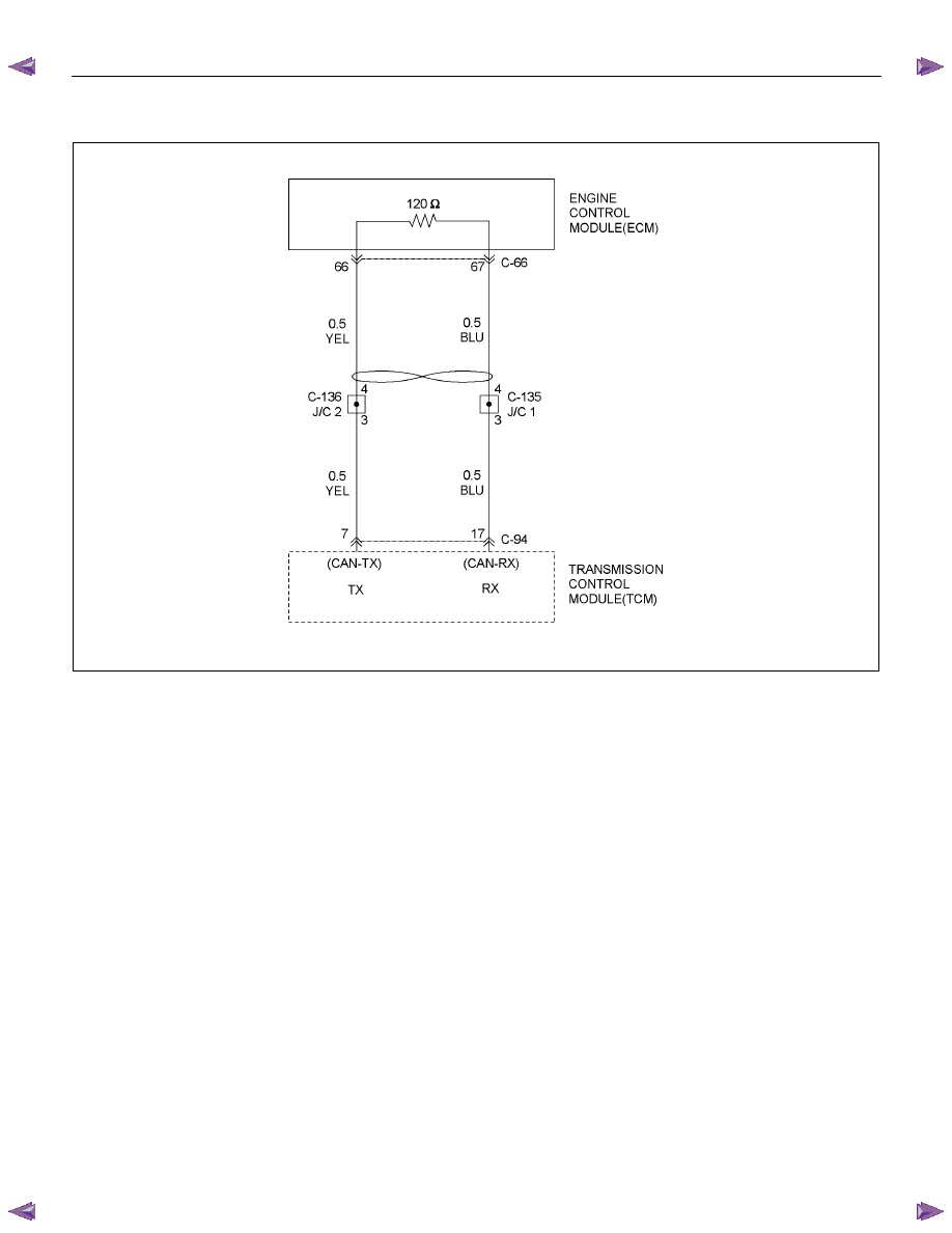
Circuit/System Testing DTCU2104
Step Action Value(s)
YES
NO
1
Was the On-Board Diagnostic (OBD) System Check
performed?
— Go
to
Step 2
Go to OBD
System Check
2
1. Install a scan tool.
2. Turn “ON” the ignition.
Does a scan tool indicate DTC U2104?
— Go
to
Step 3
Refer to
Diagnostic Aids
3
Observe the data from the ECM on the scan tool.
Was the data from the ECM fixed or did not
synchronized? (throttle opening, engine speed, etc)
—
Go to step 4
Refer to
Diagnostic Aids
4
Check the wire between the TCM connector and the
ECM connector by 5-8840-0285-0 DMM.
1. Turn “OFF” the ignition.
2. Disconnect the TCM connector.
3. Measure the resistance between terminal C94-7
and terminal C94-17.
Is the resistance specified value?
About 60
Ω
Go to Step 7
Go to Step 5
5
Check the resistance of the ECM.
1. Turn “OFF” the ignition.
2. Disconnect the ECM connector.
3. Measure the resistance between the ECM terminal
70 and the ECM terminal 71.
Is the resistance specified value?
About 120
Ω
Go to step 6
Go to step 8
6
Replace or Repair the wire between the TCM
connector C94-7, 17 and the ECM connector E60-70,
71.
Is the action complete?
—
Go to step 9
—
7
Replace the TCM.
Important:
The replacement TCM must be
programmed (Refer to SPS for procedure).
Is the action complete?
—
Go to step 9
—
8
Replace the ECM.
Important:
The replacement ECM must be
programmed (Refer to SPS for procedure).
Is the action complete?
—
Go to step 9
—

TRANSMISSION CONTROL SYSTEM (AW30–40LE) 7A2-115
Step Action Value(s)
YES
NO
9
1. Reconnect all previously disconnected harness
connector(s).
2. Clear the DTCs with a scan tool.
3. Turn “OFF” the ignition.
4. Start the engine.
5. Operate the vehicle within the Conditions For
Running the DTC. You may also operate the
vehicle within the conditions that you observed
from the Freeze Frame/ Failure Records.
Did the DTC fail this ignition?
— Go
to
Step 2 Go
to
Step 10
10
Observe the stored information, Capture info with a
scan tool.
Are there any DTCs that you have not diagnosed?
— Go
to
Diagnostic
Trouble Code
(DTC) List
Verify repair
7A2-116 TRANSMISSION CONTROL SYSTEM (AW30–40LE)
DTC U2105 (Flash Code 67)
RTW77AMF000801
Circuit Description
The automatic transmission control system in AW30-
40LE uses high speed CAN bus system. The individual
CAN bus systems are connected via two interfaces and
can exchange information and data. This allows control
modules that are connected to different CAN bus
systems to communicate. Transmission control
modules in the vehicle that require continuous, rapid
communication are connected to the high speed CAN
bus. The automatic transmission is continuously notified
of the current engine load status. Since the automatic
transmission control module has to react immediately to
load status changes, rapid communication is required
between the engine control module and the automatic
transmission control module. The high speed CAN bus
in the AW30-40LE is designed as a two-wire CAN bus
(twisted pair). The wires are shielded and twisted. The
transmission rate is 500K band.
Condition For Running The DTC
All of the following conditions are met.
(1) The following condition is met for 2 seconds or
more continuously.
• The supply voltage is more than 10.2 volts and
less than 15.5 volts.
(2) One of the following conditions is met once after
ignition “ON”.
• Output revolution sensor is not detecting failure
or not deciding failure.
Output revolution is more than 550rpm.
• Input revolution sensor is not detecting failure or
not deciding failure.
Input revolution is more than 550rpm.
• DTC U2104 is not detecting failure or not
deciding failure U2105.
DTC U2105 is not detecting failure or not
deciding or not deciding failure.
Engine revolution signal is not detecting failure
or not deciding failure.
The engine revolution is more than 550rpm.
TRANSMISSION CONTROL SYSTEM (AW30–40LE) 7A2-117
(3) All of the following conditions are met.
• Device Control is not operating.
• Disable Normal Communication is receiving
enable.
• DTC Clear is not operating.
(4) DTC U2104 is not detecting failure or not deciding
failure.
Condition For Setting The DTC
Detection standard is met for 2.5 second continuously.
Detection standard:
If one or more ID sent from Engine Control Module
(ECM) is not completed receiving for 2 basic cycles
since last receiving completion.
Action Taken When The DTC Sets
• Throttle judgment on torque reduction control, line
pressure control at stationary status, line pressure
reduction control at gear change and line pressure
reduction control at garage. (Throttle opening 100%)
• Line pressure FULL output.
• Throttle judgment on gear change control (Throttle
opening 0%).
• No line pressure reduction control at gear change.
• No torque reduction control.
• No squat control.
• No slope control (keep mode).
• No L-up control.
• Control Engine rpm at 7000rpm (No inertia
calculation).
• Control actual torque at MAX.
• Control driver torque at MAX.
• Control engine coolant temperature at 80
°C (176°F).
• No coast control.
• No 3rd Start mode control.
• No line pressure reduction control at garage.
• No output revolution sensor failure detection.
• No C-0 rev sensor failure detection.
• No selector position switch failure detection.
• No oil temperature sensor failure detection.
• No T/F Hi-Low SW failure detection (Execute T/F
judgment using only T/F-SW).
• No speed mater signal failure detection.
• No throttle signal failure detection.
• No Engine torque signal failure detection.
• No engine coolant temperature signal failure
detection.
• No Engine revolution signal failure detection.
• No shift solenoid functional failure detection.
• No L-up solenoid functional failure detection.
• Cancel engine rpm condition of prerequisite of supply
voltage failure detection.
• Control vehicle speed of speed meter at 0km/h.
• No torque reduction at stall.
• No cruise control.
• No warm up control.
• Check Trans “ON”.
• DTC stored.
• MIL request “ON”. (EURO 4 only)
Conditions For Clearing The DTC
• The DTC can be cleared from the TCM history by
using a scan tool.
• The DTC will be cleared from history when the
vehicle has achieved 40 warm-up cycles without a
failure reported.
• After more than 1 second has elapsed after the
ignition key has been turned “ON”, short between
No.11 and No.4 (ground) of DLC (Data Link
Connector). Then, after 1 second, but within 6
seconds, discontinue shorting.
Diagnostic Aids
• Inspect the wiring for poor electrical connection at the
TCM. Look for possible bent, backed out, deformed
or damaged terminals. Check for weak terminal
tension as well. Also check for a chafed wire that
could short to bare metal or other wiring. Inspect for a
broken wire inside the insulation.
• When diagnosing for a possible intermittent short or
open condition, move the wiring harness while
observing test equipment for a change.
• Inspect the wiring for EMI (Electro-Magnetic
Interference). Check that all wires are properly routed
away from coil, and generator. Also check for
improperly installed electrical options. When this test
is performed, turn “OFF” on electronic auto parts
switches to improperly for a noise preventing.
Нет комментариевНе стесняйтесь поделиться с нами вашим ценным мнением.
Текст