Isuzu KB P190. Manual — part 1018

7A2-106 TRANSMISSION CONTROL SYSTEM (AW30–40LE)
(4) All of the following conditions are met.
• Device Control is not operating.
• Disable Normal Communication is receiving
enable.
• DTC Clear is not operating.
Condition For Setting The DTC
The TCM detects following conditions for 0.5 seconds
continuously at shifting.
• Voltage at connector pin is 0V when solenoid is “ON”.
(DTC P2769)
• Voltage at connector pin is ignition voltage when
solenoid is “OFF”. (DTC P2770)
Action Taken When The DTC Sets
• No L-up solenoid functional failure detection.
• No squat control. (DTC P2770)
• The TCM fixes to 1st gear when the vehicle speed is
less than 10 km/h (6 mph).
• Check Trans “ON”.
• DTC
stored.
• MIL request “ON”. (EURO 4 only)
Conditions For Clearing The DTC
• The DTC can be cleared from the TCM history by
using a scan tool.
• The DTC will be cleared from history when the
vehicle has achieved 40 warm-up cycles without a
failure reported.
• After more than 1 second has elapsed after the
ignition key has been turned “ON”, short between
No.11 and No.5 (ground) of DLC (Data Link
Connector). Then, after 1 second, but within 6
seconds, discontinue shorting.
Diagnostic Aids
• Inspect the wiring for poor electrical connection at the
TCM. Look for possible bent, backed out, deformed
or damaged terminals. Check for weak terminal
tension as well. Also check for a chafed wire that
could short to bare metal or other wiring. Inspect for a
broken wire inside the insulation.
• When diagnosing for a possible intermittent short or
open condition, move the wiring harness while
observing test equipment for a change.
Circuit/System Testing DTC P2769 or P2770
Step Action Value(s)
YES
NO
1
Was the On-Board Diagnostic (OBD) System Check
performed?
— Go
to
Step 2
Go to OBD
System Check
2
1. Install a scan tool.
2. Start the engine.
3. Drive the vehicle in D position.
4.
Accelerate the vehicle until the gear position
becomes the 4th.
5. Release the accelerator pedal and accelerate the
vehicle until the gear position becomes the 4th
again.
Does a scan tool indicate DTC P2769 or P2770?
— Go
to
Step 3
Refer to
Diagnostic Aids

TRANSMISSION CONTROL SYSTEM (AW30–40LE) 7A2-107
Step Action Value(s)
YES
NO
3
1. Turn “ON” the ignition with the engine “ON”.
2. Place the selector lever in the “P” position.
3. Measure the voltage between terminal C94-5 and
terminal C94-1 on the TCM pigtail connector by 5-
8840-0285-0 DMM.
Is the voltage specified value?
8
∼
16V Go
to
Step 4
Go to Step 5
4
1. Turn “OFF” the ignition.
2. Disconnect the TCM connector (C-94).
3. Turn “ON” the ignition.
4. Measure the voltage between terminal C94-5 and
terminal C94-1 by 5-8840-0285-0 DMM.
Is the voltage specified value?
8
∼
16V Go
to
Step 7
Go to Step 10
5
1. Turn “OFF” the ignition.
2. Measure the resistance between terminal C94-5
and body ground by 5-8840-0285-0 DMM.
Is the resistance specified value?
11
∼15Ω Go
to
Step 9
Go to Step 6
6
1. Disconnect the automatic transmission connector
(E-54).
2. Measure the resistance between terminal E54-7
and body ground by 5-8840-0285-0 DMM.
Is the resistance specified value?
11
∼15Ω Go
to
Step 7
Go to Step 8
7
1. Check for open or short in the wire between
terminal C94-5 and terminal E54-7.
2. Repair or replace the wire between terminal C94-5
and terminal E54-7.
Is the action complete?
— Go
to
Step 11 —
8
Replace the SL solenoid.
Is the action complete?
— Go
to
Step 11 —
9
1. Clear the DTC.
2. Perform the test-driving.
3. Check the DTC.
Was DTC P2769 or P2770 stored?
— Go
to
Step 10
Refer to
Diagnostic Aids
10
Replace the TCM.
Important: The replacement TCM must be
programmed (Refer to SPS for procedure).
Is the action complete?
— Go
to
Step 11 —

7A2-108 TRANSMISSION CONTROL SYSTEM (AW30–40LE)
Step Action Value(s)
YES
NO
11
1. Reconnect all previously disconnected harness
connector(s).
2. Clear the DTCs with a scan tool.
3. Turn “OFF” the ignition.
4. Start the engine.
5. Operate the vehicle within the Conditions For
Running the DTC. You may also operate the
vehicle within the conditions that you observed
from the Freeze Frame/ Failure Records.
Did the DTC fail this ignition?
— Go
to
Step 2 Go
to
Step 12
12
Observe the stored information, Capture info with a
scan tool.
Are there any DTCs that you have not diagnosed?
— Go
to
Diagnostic
Trouble Code
(DTC) List
Verify repair
TRANSMISSION CONTROL SYSTEM (AW30–40LE) 7A2-109
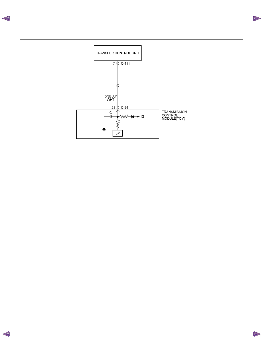
DTC P2773 or 2774 (Flash Code 75)
RTW77AMF000901
Condition For Running The DTC
All of the following conditions are met.
(1) All of the following conditions are met for 2
seconds or more continuously.
• The supply voltage is more than 10.2 volts and
less than 15.5 volts.
• DTC U2104 is not detecting failure or not
deciding failure.
• DTC U2105 is not detecting failure or not
deciding failure.
• Engine revolution signal is not detecting failure
or not deciding.
• The engine revolution is more than 550 rpm.
(2) Not emergency mode.
(3) D, 3, 2, L position point is “ON”.
(4) Shift position signal is not detecting failure or not
deciding failure.
(5) The vehicle speed is more than 29 km/h (18 mph)
and less than 160 km/h (100 mph).
(6) Speed meter signal is detecting failure or not
deciding failure.
(7) Output revolution rpm is more than 1500 rpm.
(8) Output revolution sensor is not detecting failure or
not deciding failure.
(9) Throttle opening more than 2%.
(10) Throttle opening signal is not detecting failure or
note deciding failure.
(11) All of the following conditions are met.
• Device Control is not operating.
• Disable Normal Communication is receiving
enable.
• DTC Clear is not operating.
Condition For Setting The DTC
All of the following conditions are met for 10 seconds
continuously. (DTC P2773)
• Transfer 4L switch is “ON”.
• Transfer High judgment by transfer real gear ratio 0.9
< T/F Hi gear ratio < 1.1
All of the following conditions are met for 10 seconds
continuously. (DTC P2774)
• Transfer 4L switch is “OFF”.
• Transfer Low judgment by transfer real gear ratio
2.23 < T/F Low gear ratio < 2.73
Action Taken When The DTC Sets
• No shift solenoid functional failure detection.
• No L-up solenoid functional failure detection.
• MIL request “ON”.
• Check Trans “ON”.
• DTC
stored.
• MIL request “ON”. (EURO 4 only)
Нет комментариевНе стесняйтесь поделиться с нами вашим ценным мнением.
Текст